Steps I took that resulted in the problem:
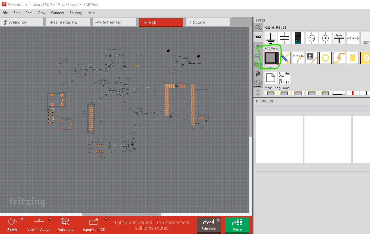
Schematic created, PCV view worked a few days. One day the copper and connections partially and randomly disappeared. Nothing on PCB can select where there is no orange. No obvious change or action. Schematic view appears to work and connect on parts that are not connectable in PCB view.
I have paid and downloaded v1.05, but am hesitant, as the last upgrade lost a lot of work or would not integrate to new version. 
…
What I expected should have happened instead:
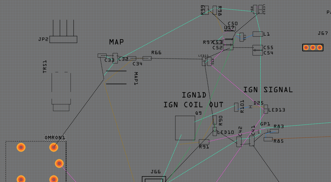
I expected a normal view, but have the image below.
…
My version of Fritzing and my operating system:
v1.02 Win10
…
Please also attach any files that help explaining this problem
1.0.5 should upgrade without issues (it has always done so for me.) Something else went wrong (probably corruption in the user directories on your upgrade and/or the parts were broken.) That said you need to upload the sketch (the .fzz file, upload is 7th icon from the left in the reply menu) as pictures are basically useless when trying to diagnose a problem. If you are using parts from the net (as opposed to parts in core parts which have in theory been vetted, although that is not always true) it is possible the parts have problems.
Peter
Peter
Peter
I’ve been on the upgrade for quite a while with no issues until now. The file below is the one, but I opened the parent file it was created from without issues. That file works fine. I also added a new part (from you) to the pooched file to see if it made a difference overall - which it did not - but did import properly and appears properly while the other parts are still broken in PCV view.
Oh, and the schematic is mostly OK, but several parts have moved placement, and some connections are ‘different’, e.g. a capacitor has both + and – on the same trace.  Any advice how to rebuild this file with minimum days involved? Is there a way to test the Fritzing program files are all OK moving forward?
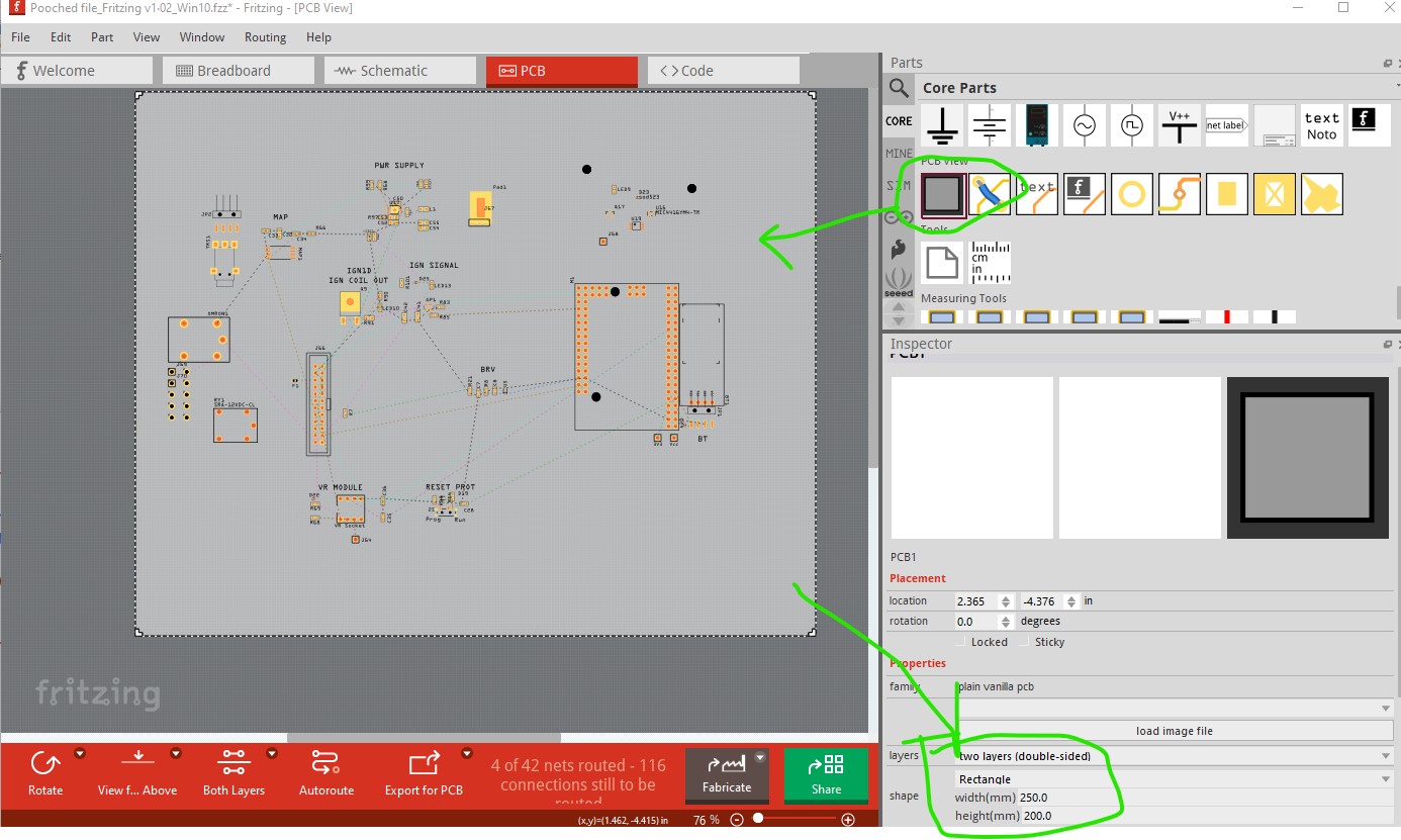
Well it is certainly broken. Luckily also easily fixed. What happened is that you deleted the pcb rectangle and apparently made it single sided (so the SMD parts don’t have a copper1 layer to appear on. Dragging a pcb rectangle back in setting it to double sided and increasing its size fixes things:
The original sketch:
what it should look like (you will need to adjust the size of the pcb to suit what you want I just made it larger than the parts.) Initially the SMD parts were still missing because the board was set to single sided.
Peter
Thanks! Will try that now…