PCB view, IC with package SO(w)16

Steps I took that resulted in the problem:

I selected the generic “IC” part and added it in the PCB view. Then I changed the package to “SO(w)” with 16pins.

What I expected should have happened instead:

The IC’s connection pads should be accessible, however they seem to be overlapped by black bars. See the attached screenshot for details.

My version of Fritzing and my operating system:

Fritzing v0.9.3 on macOS 10.15.6

Main question:

What could I do to remove the black bars, so the pins can be used on the PCB?

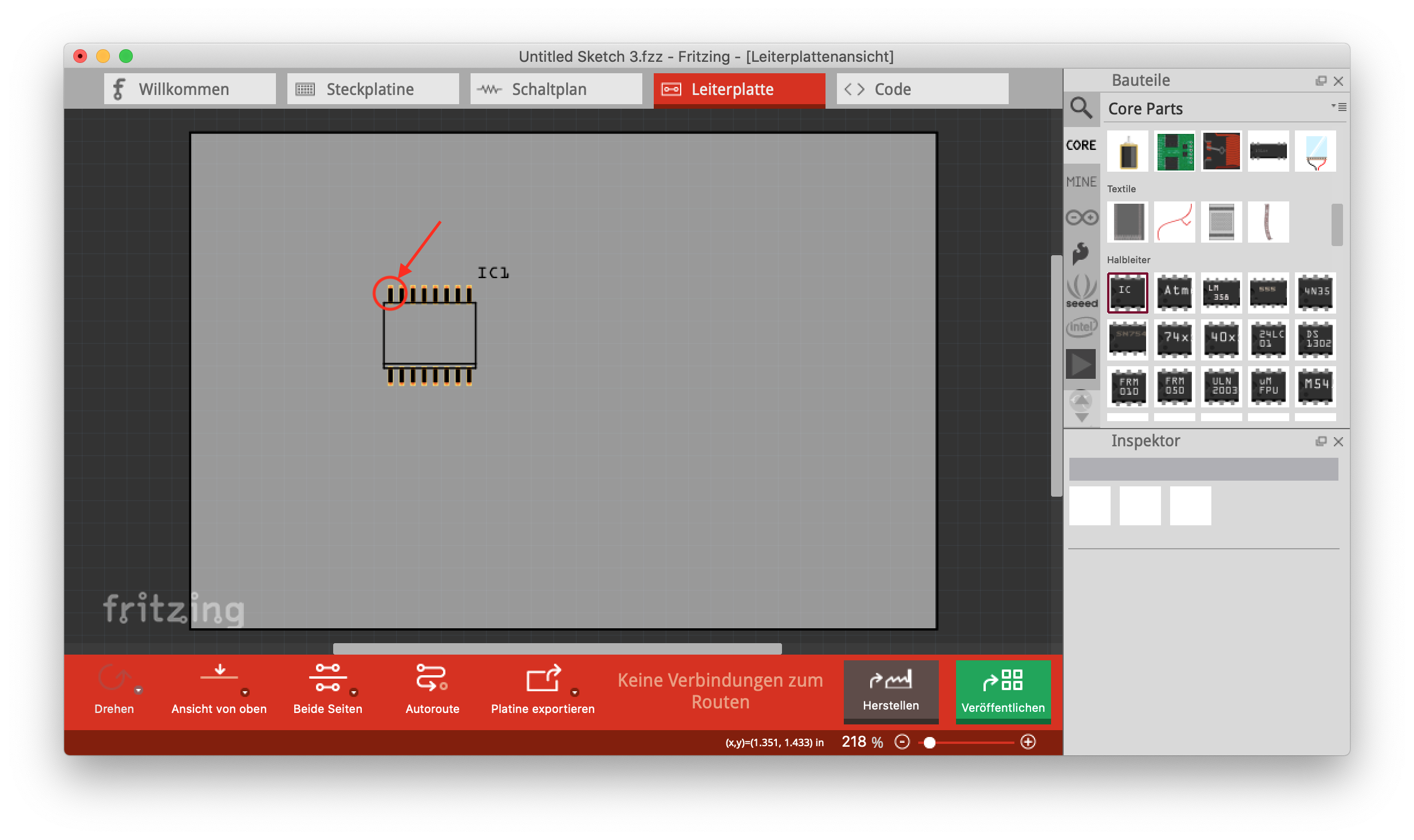
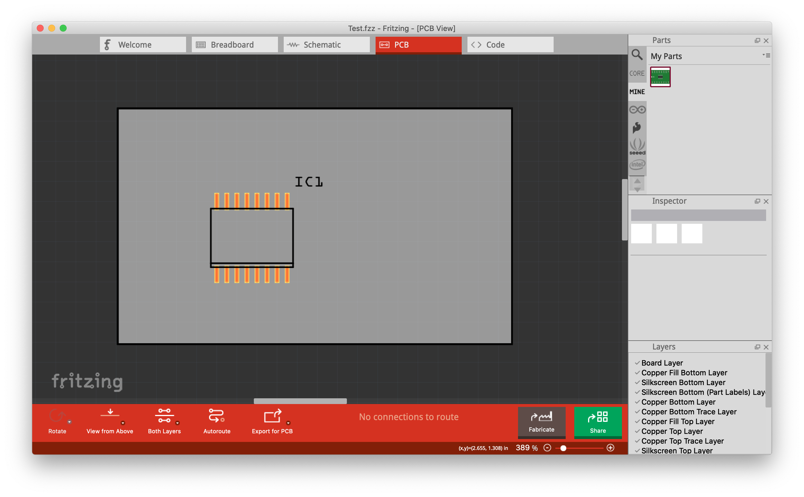
This is likely an error in the part definition. The first thing I would try is export the sketch to a gerber and check the gerber output to see if the black bars are suppressed. If not, you or one of us would need to fix up the pcb svg file.

Peter

Hi Peter,

thanks for the hint that it is an svg file issue.

I fixed the svg file (just commented out the black bars, which should not be there).

The fixed part file is attached to this post.

SO16w.fzpz (6.7 KB)

For me, it is working now.
How can the part be integrated into Fritzing for others?

Regards,
Max

You would need to make a pull request against the core part in the fritzing-parts repository on github. This should be an easy enough change that you shouldn’t have issues about obsoleting the original part (which isn’t documented as far as I know.)

Peter

Hi Peter,

I just created a pull request: https://github.com/fritzing/fritzing-parts/pull/258

Regards,
Max