I’m relatively new to Fritzing but I have already successfully designed a couple PCBs and used the exported gerber files to cnc them. Works great so far.
However, the thing I really can’t get my head around, even when considering various different coordinate offset philosophies, is the resulting placement of parts when their location (inch or mm) is specified manually.
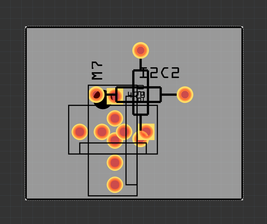
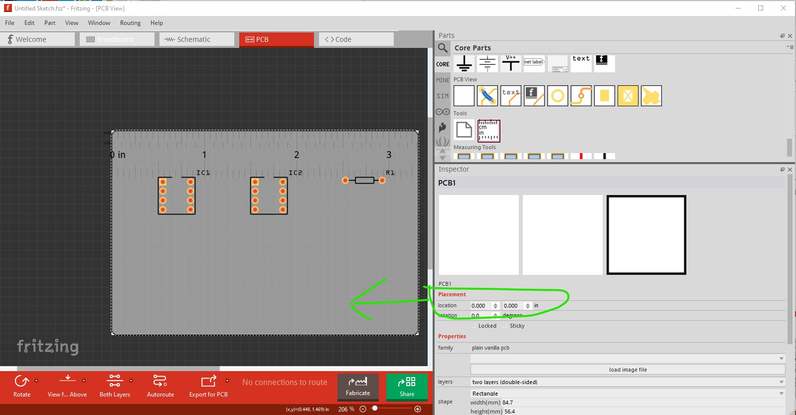
The image shows various parts, all placed at location (0.0, 0.0), incl the rectangular PCB. Observations:
None of their pins align with the grid (Ideally, I would expect that one of the pins is used as the origin in the part’s reference frame, because that’s more important than any symbol representing the part).
Not even the bounding box (which is completely arbitrary anyway) aligns with anything (except the hole’s). Not in a logical way at least.
The PCB rectangle placement seems to have a fixed but completely arbitrary offset (its internal origin being somewhere inside the rectangle, not at a corner, not in the center)
It would be fine if it would be possible to let the corners of the PCB rectangle snap to the grid. Using the grid when placing parts with the mouse works fine for me. But without the grid snap, or consistent origin, I cannot place the PCB rectangle accurately. This renders the design + manufacturing of e.g. two-sided PCBs without alignment holes, or any PCB where part placement relative to the PCB is crucial very difficult.
Did I miss something here? How can I place the PCB rectangle in an accurate controlled way?
I went through all location and units options and searched the docs and forum for hints but could not find anything that would help me here.
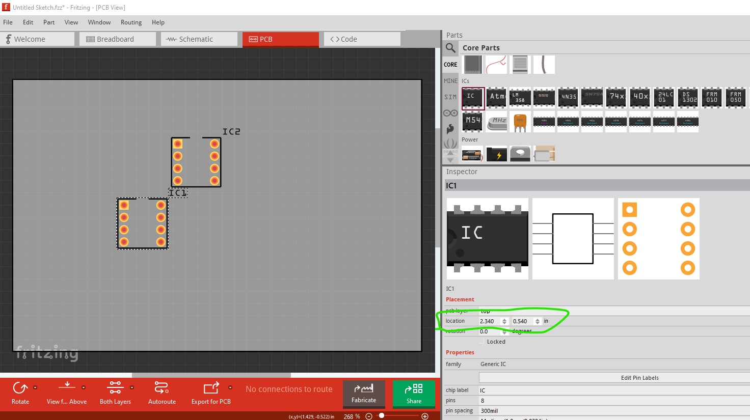
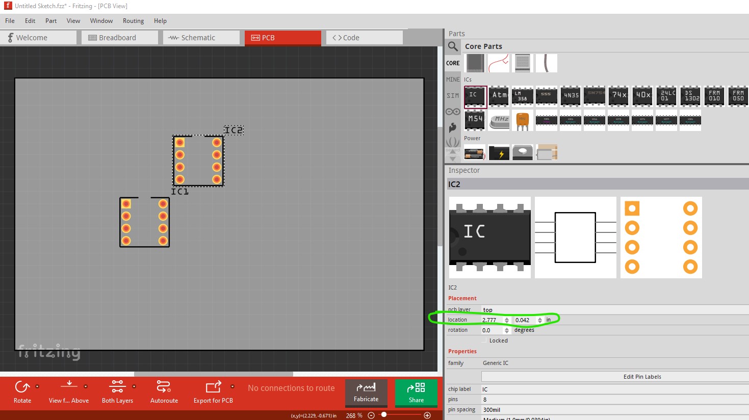
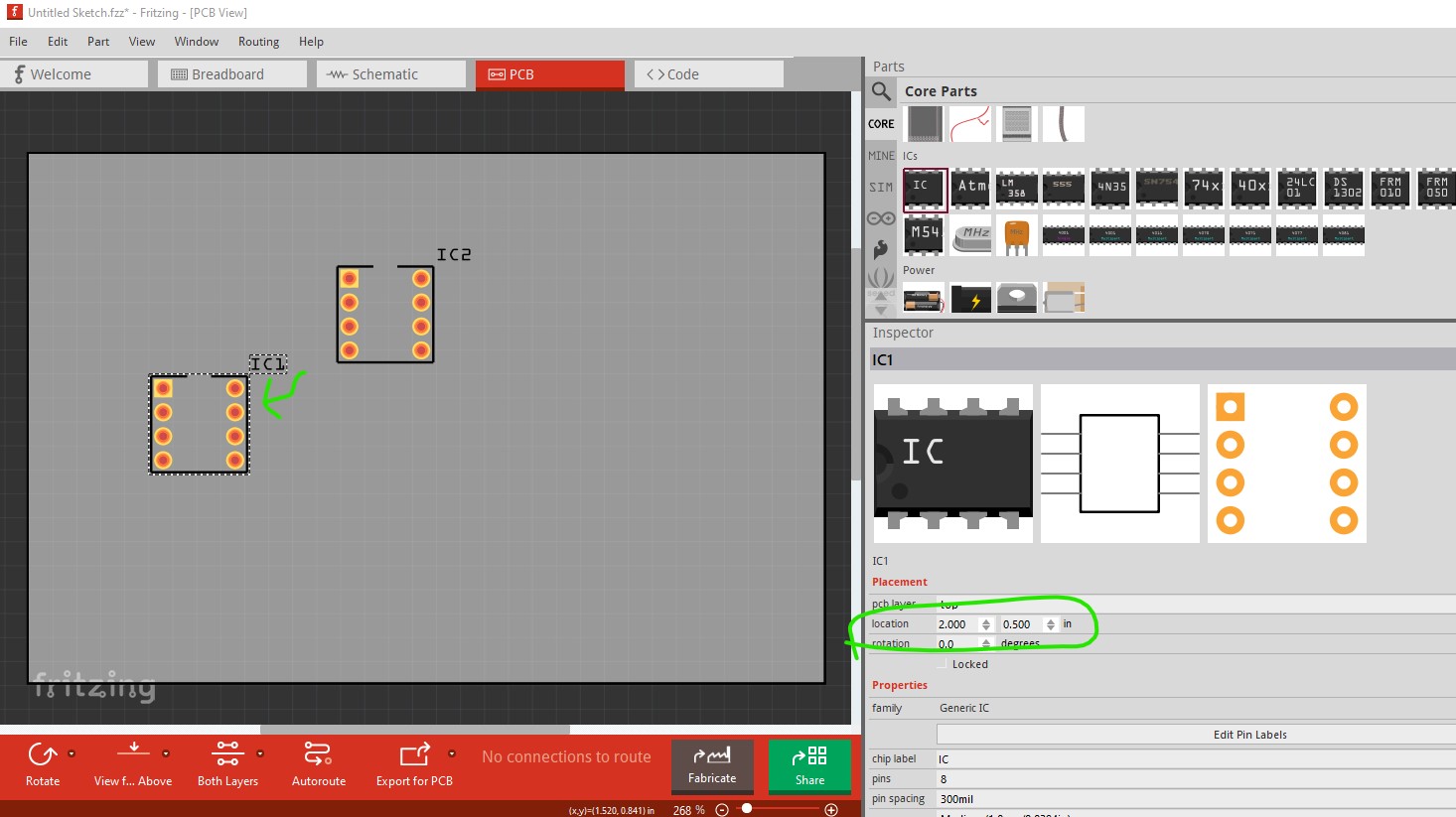
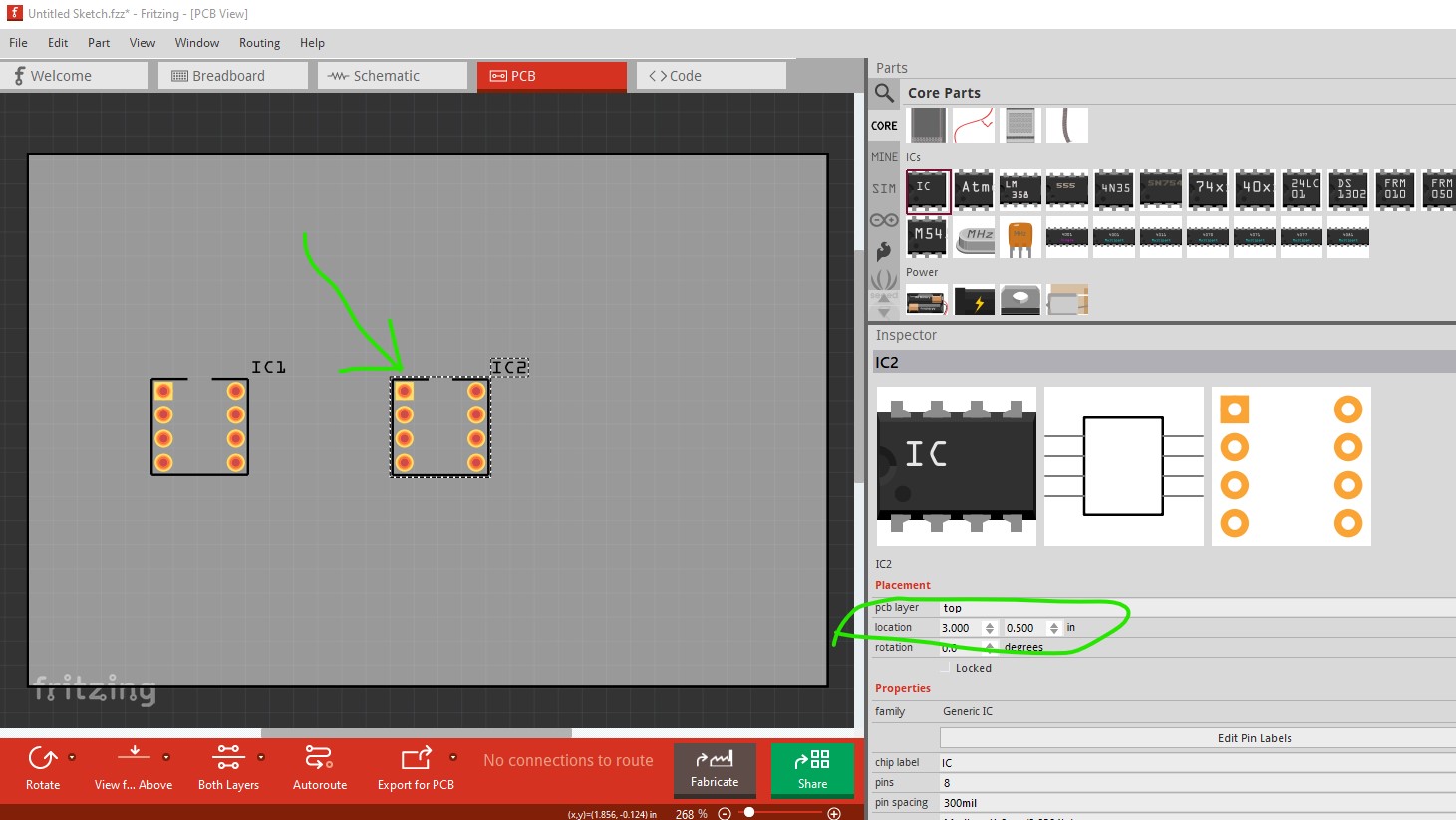
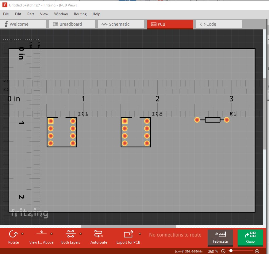
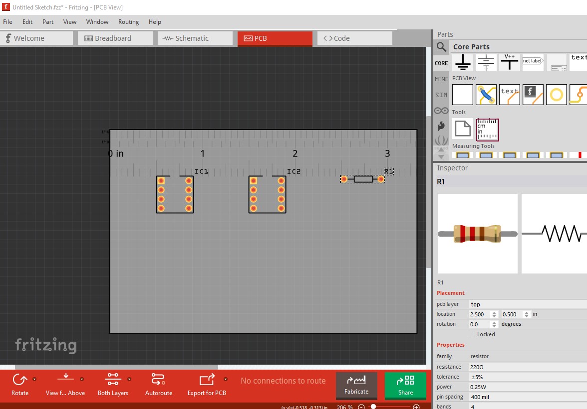
two ICs randomly placed (note this if Fritzing 1.0.2 so scaling works correctly!) The positions are circled in green in the Inspector window on the bottom right. Changing them there moves the part like this (which may do what you want.)
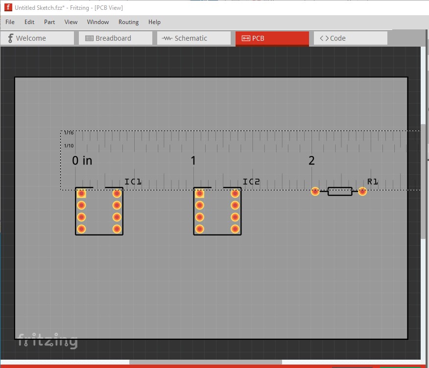
although it isn’t clear what the start reference is (I would have expected the top edge of the pcb but that apparently isn’t the case! The spacing however appears correct.)
Then it works correctly. On earilier Fritzing versions a scaling issue made the settings imprecise unless the view is scrolled all the way out (which is a PITA!) so it is worthwhile to upgrade to the latest version if you haven’t already (for routing database corruption issues that have been fixed as well!)
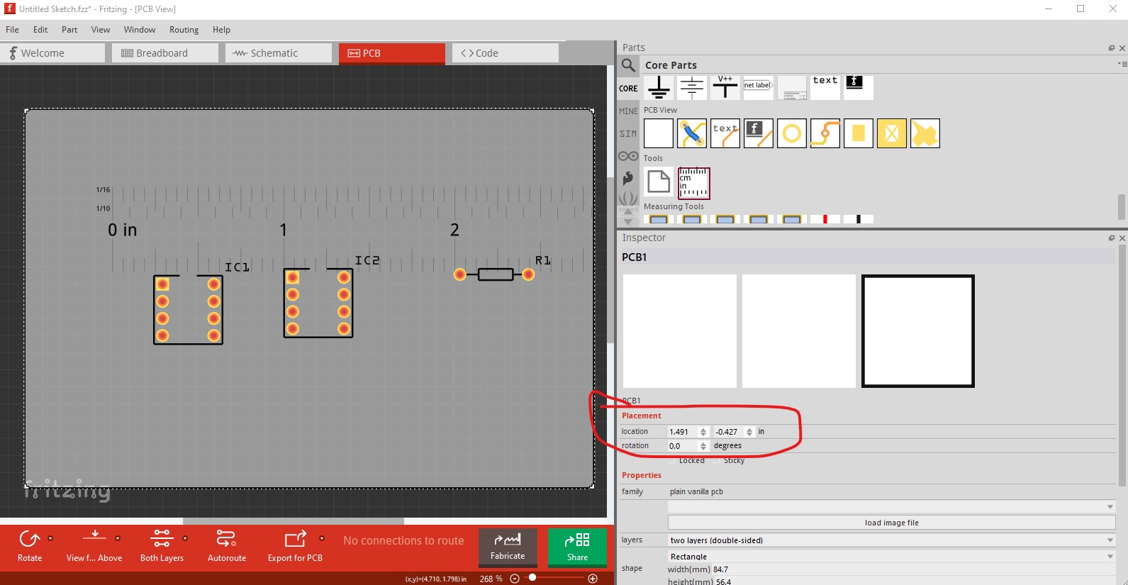
Using the latest version indeed solves my problem! The origin of the PCB rectangle can be set accurately in the inspector now and corresponds to the top left corner of the PCB. Perfect!
I had used the version that’s in the Ubuntu 22.04 deb repositories so far (0.96) which lags behind the AppImage release directly from Fritzing. Having the latest version is absolutely worth paying for! Keep up the good work!