Now that I have a PCB designed and created, is there a way to get this PCB into the parts bin so that I can drag it next to the breadboard, on the page to start a new project?
I’m not clear what you are asking. You have the triangle sketch (I’m assuming) and you want to use that as the start of a new project? A sketch is different than a part, a sketch could be made in to a part with a fair amount of effort I expect but it isn’t usual. You can load the sketch and then make changes to it for a new project, but because the sketch isn’t a part it won’t go in to the parts bins.
Peter
Yes, used the wrong word, script, should have been a new project. It would be a part that would be in a bin that could be searched.
Basically, how does Adafruit or Arduino get their parts so that they show up in the bins and able to drag and drop next to the beardboard. ie: Uno or Neopixel 24 circle.
Yes the triangle sketch. Is this something that Inkscape is use for?
That is because they are parts (as opposed to a sketch which your triangle currently is.) By default a new part will show up in your mine parts bin, to get it in another bin you need to create a bin file (which Adafruit has done for their parts.) To change your triangle to a part will take some work as essentially you need to import all the parts in your sketch in to a single svg and then arrange the required interconnections (typically parts don’t have interconnections, but it is possible to create them. ) It would be a very large part I expect and may cause performance problems. Yes Inkscape (or another svg editor) is the usual way to make parts as you need to create svg files for the part. Actually come to think of it I don’t know of a way to do the triangle shape in a part. AFAIK the shape can only be specified in a sketch I don’t think there is a way to get the shape in to a part to modify the gerber output to cut the shape which looks to rule out making it a part unless someone else has a way.
Peter
What is you want to be able to do with the “triangle as a part”?
‘stamp’ it multiple times on a (very) large PCB? I think that would hit limits on the size of PCB that Fritzing can work with. The footprint, with all of the LED contact points should be possible. I do not know about get the traces between into the sketch from the part though.
Use multiple triangles in a single project? To add a microcontroller to generate the singles needed for the triangles?
That would be possible. Most of the complexity for the triangle does not matter at all for this case. All that ‘needs’ to be in the different part views are the connection points. Power, ground, and data. Both in and out. There is probably no use for a PCB view at all. A triangle ‘part’ would not mount on another PCB. Unless you wanted to have a header footprints for the input and output connections. Since the LED’s chain, all the schematic needs is the input power and data pins for a single LED, and the final output if chaining signal to the next triangle. Same for breadboard. It is just an image, with input and output connectors. Nothing in the middle matters to Fritzing.
If you wanted to add Spice data, to be able simulated the full part, that could get more complicated. I don’t know spice to be able to guess what that would take. I think sub modules can be built up to combine things into a module, but don’t know how to go about that.
Yes, this it what I want to do. I wanted to create a write-up on my project and use Fritizing to aid in this.
There would be 2 copies of the triangle on the screen attached to a breadboard and micro controller.
That means that a much simplified triangle can be used for the part. Possibly the breadboard image for the part could be taken from an (svg) export of the pcb for the triangle sketch (fzz). No pcb is needed for the part. Schematic and breadboard only need the power, ground, and data connections. Breadboard just needs the connection points relatively accurately positioned.
1 Like
That is much easier than making the full triangle in to a part. As @microMerlin said you only need an image of the triangle (not all the internal parts) and the connectors. The internal connections only show up on breadboard. To make this part I loaded the Triangle_24-LED-v9.00.fzz sketch then changed to pcb view and did File->export->as image->svg to get a svg of breadboard view. Unfortunately it has all the connectors (which I don’t want), fortunately this is often a problem with Eagle2Fritzing and thus I have a python script to fix it. So I selected only the8 pins I wanted (JP1 to JP3) and deleted all the rest. This became the breadboard svg. Randy’s Inkscape extension made a schematic and a part was created that looks like this

the green circles are the only connectors that exist (credit to @microMerlin for asking the correct question!) which is all you are interested in. Schematic (which I expect you won’t need) looks like this
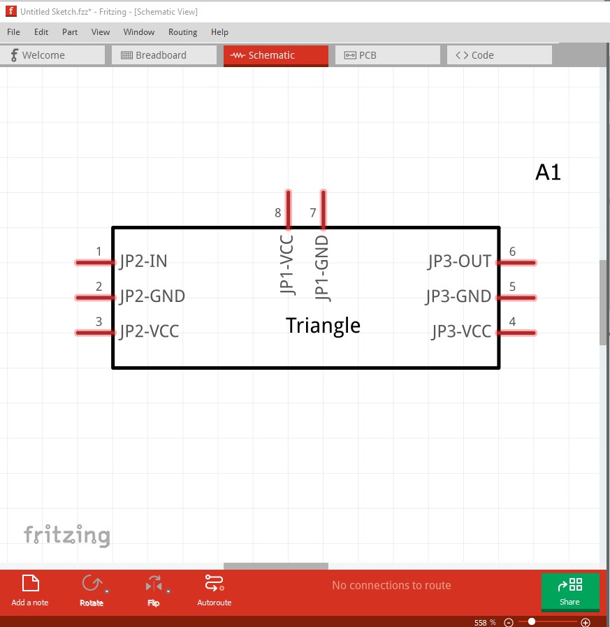
which shows the only active connections. Here is the part this came from
triangle-part.fzpz (26.5 KB)
which should do what you want.
Peter
1 Like
Thanks so very much Peter.
This is exatly what I need. Have it wired to a RPi Pico and have a Micropython script that has them blink as indended.
I had the PCB exported as a svg, but wan’t exactly sure how to get that image back into Fritzing.
Thanks again,
Scott