Yes that is the file. The complete sketch document.
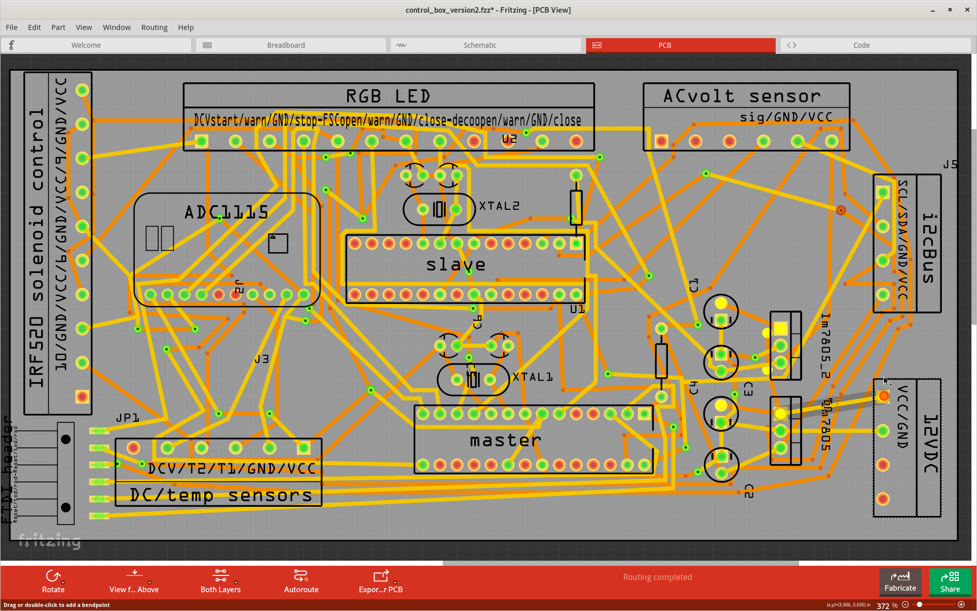
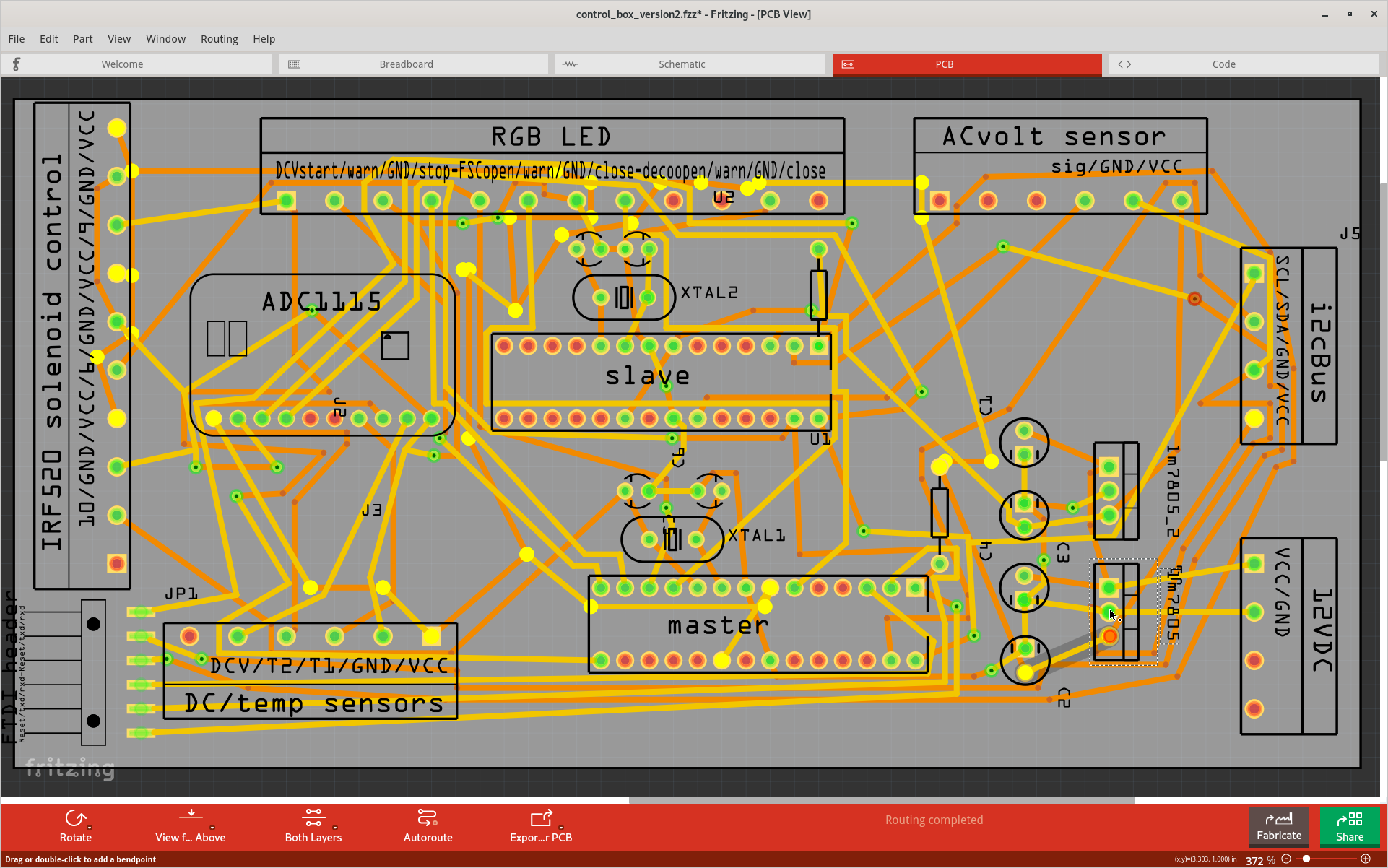
I do not understand what you mean by the %v output goes nowhere. Fritzing will highlight (in brighter yellow) vall of the connectors and wire ends it believes are connected together (into as single ‘net’) when you click and hold on any one of the connectors. Here are snapshots of what that looks like for the 12V input, GND, and each of the LM7805 regulator outputs. Without a full analysis, it look like power and ground are connecting to reasonable places.


This is definitely not a ‘finished’ board yet. On the Routing menu, Click Design Rules Check (DRC). That reports (and shows with red overlap markings) several places where the traces got too close to, or even overlapped with, some other trace/connection, which shorts them together. Some of that may be from autorouting. It is not very smart, and can ‘cut corners’ a bit too close. Others look like manually placed traces that were not properly routed to avoid connectors.