You can’t “T” connect wires in BB view, they are fake connections that don’t work. Hence the rat’s are needed to show real connections. It’s covered in the tutorial vids above.
There are definitely bugs. And not enough people (and time) to work on them. A ratsnest line (that does not really exist) that later vanishes is minor. Often just moving the part or wire that it looks like it is connected to will clean it up. Or turn off ratsnest in the view menu, and turn it back on.
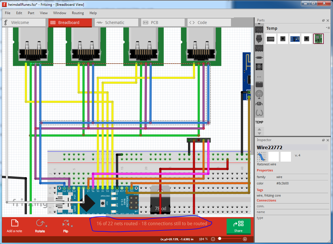
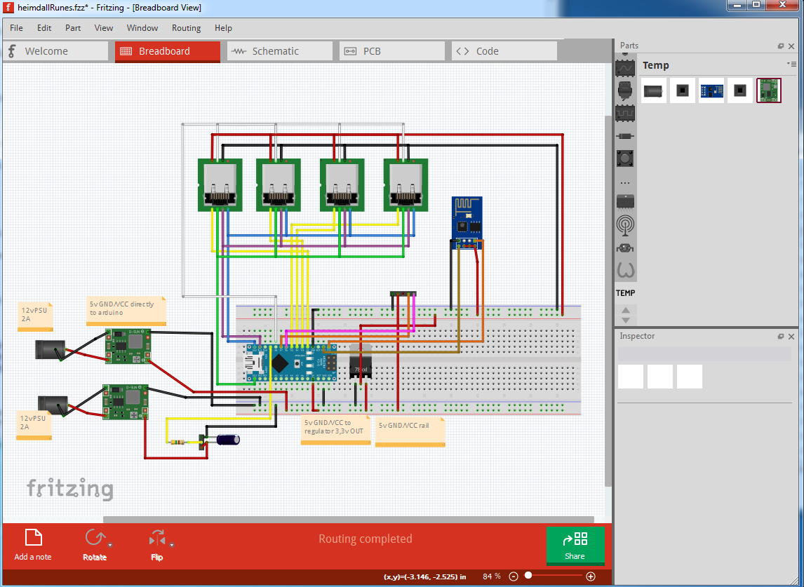
As @Old_Grey said you can only connect pins in breadboard and so some of your pins appear connected but aren’t. The message at the bottom “16 of 22 nets routed” is the clue (outlined in blue in the image below)
original:
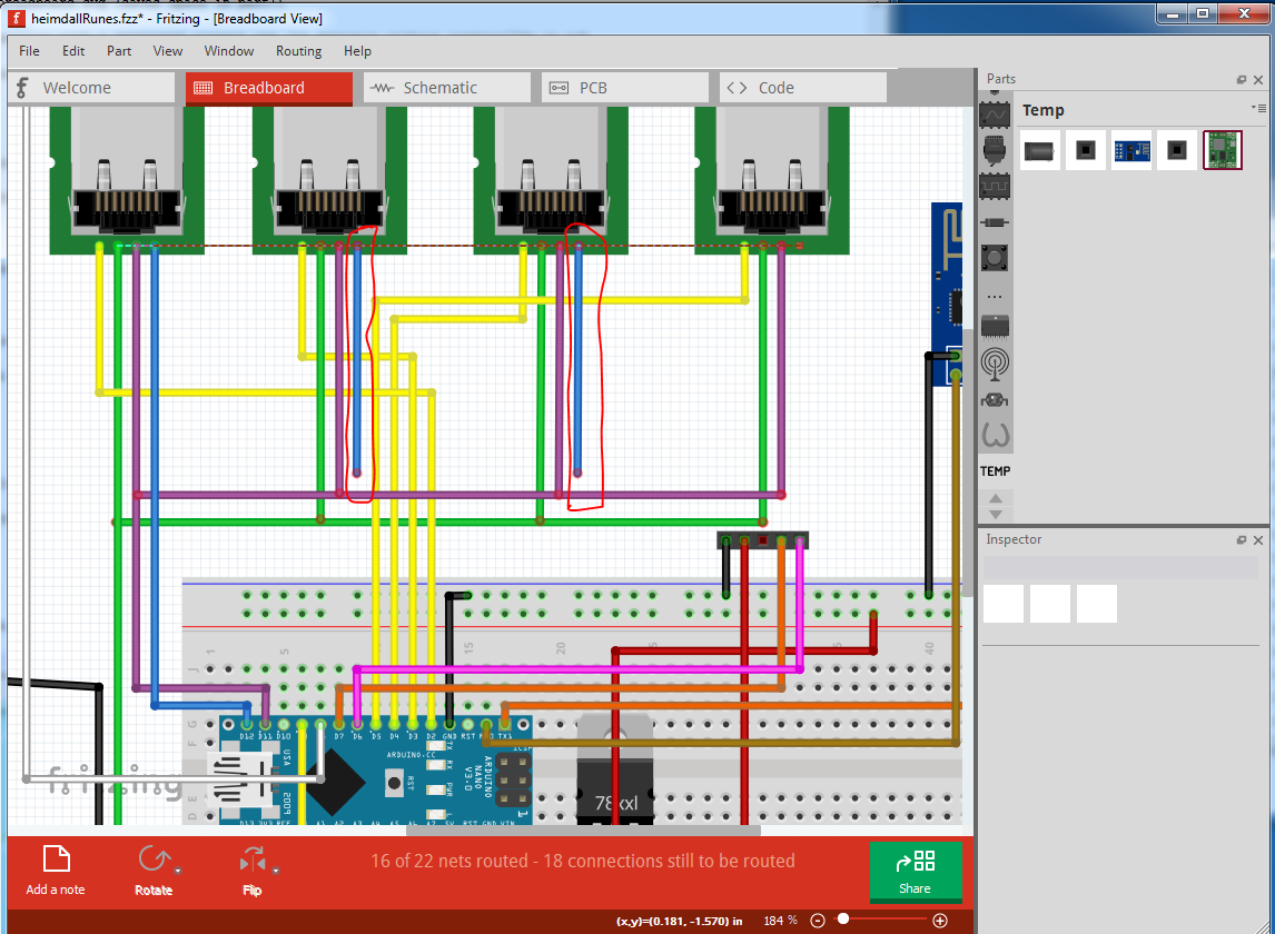
delete the selected wire and we see two wires with no connection
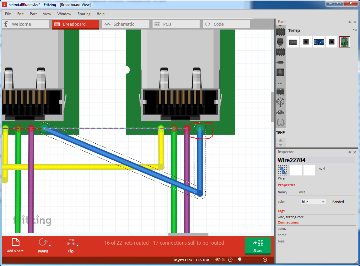
delete those two wires and select a ratsnest line near to the pin to get the connection I want to route and route it correctly. Repeat for the other two rats nest lines to complete routing the blue wire connection.
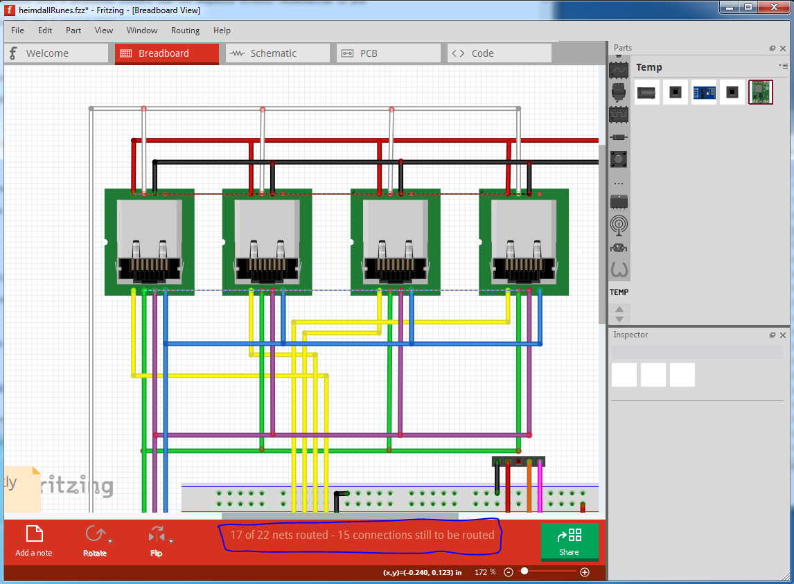
When that is done, the routed / unrouted net counts change by one and the associated rats nest lines go away.
repeating that for all the rest of the rats nest lines corrects the problem and produces routing complete and no extra rats nest lines. Note it isn’t always this easy, it is possible (although so far not reproducable) to corrupt the routing data base in which case you need to delete all traces in all views and reroute the board. The best practice is to do all the routing in a single view and then route the rats nest lines in the other 2 views.
Peter
A minor variation of peter’s routing is a bit messier, but shows much more clearly that the wires are only attacting to connectors (pins).
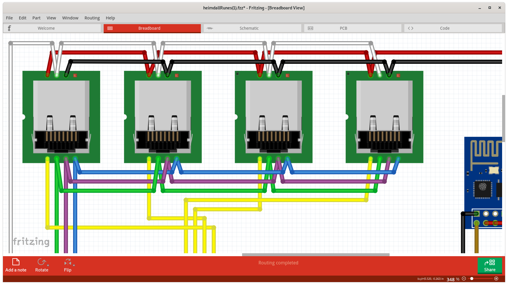
Changing the order that the RJ45 jacks appear can simplify the data line connections.
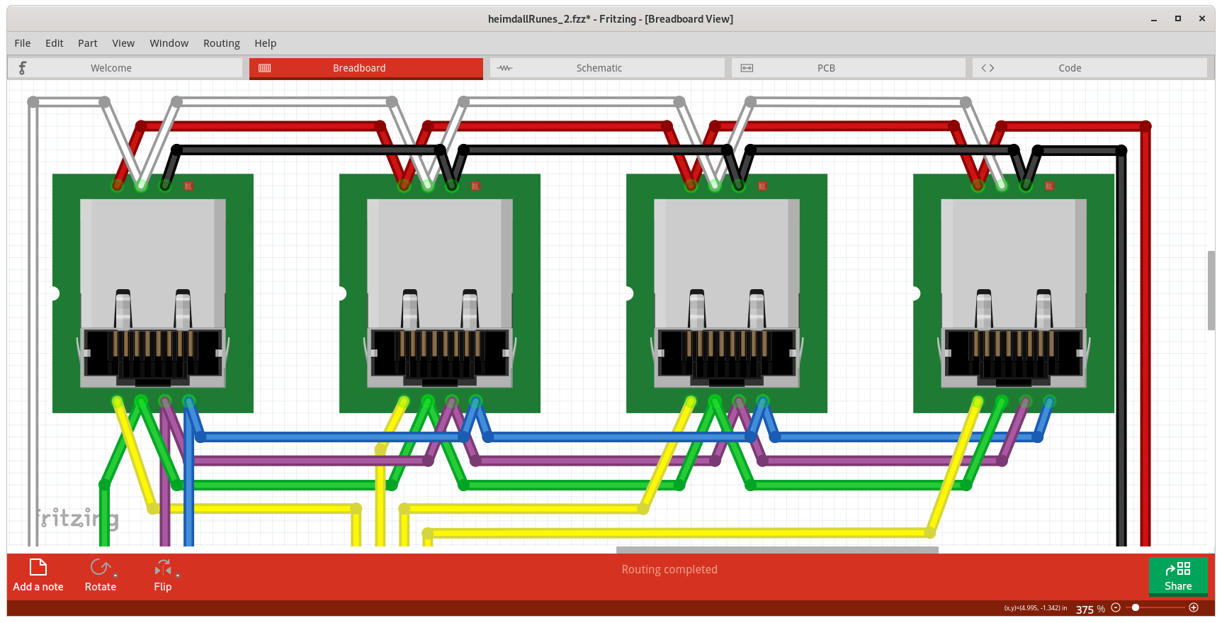
More moving of parts and routing of the wires gets to
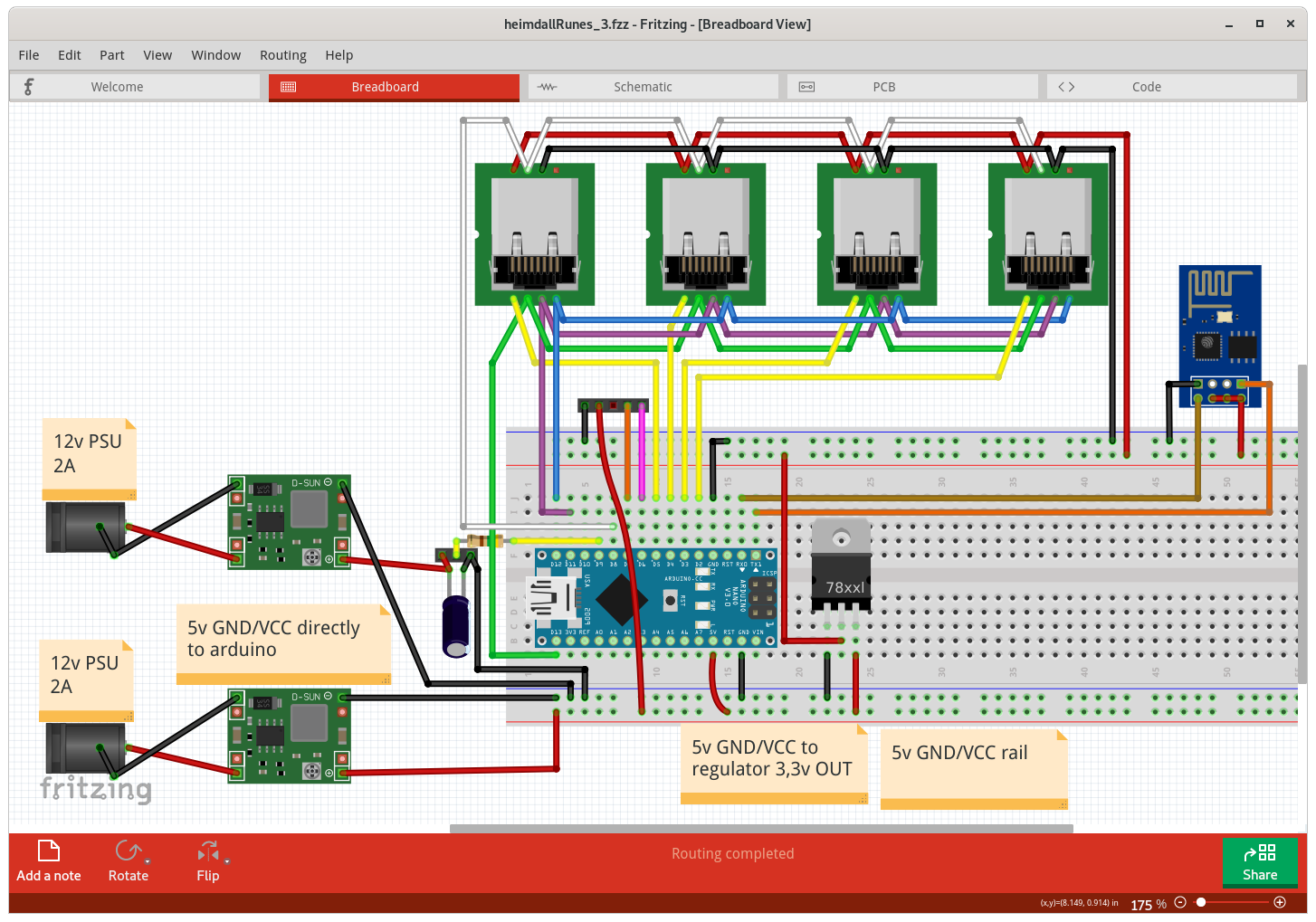
Notice in that, that the wires can be curved, instead of only using sharp corners. That was done to keep the general layout close to the original, but reduce the cases where wires are crossing. Here is the sketch file that matches the above.
heimdallRunes_3.fzz (119.2 KB)
Hi all,
First let me thank you all the hard efford you did with me on this.
Few months have past since I started this trhead and I finally managed to get my PCB with me. I have been waiting 3 weeks for few PCB, several projects, but the most difficult one was this one.
After soldering all the components and uploading the code to Arduino I tested up the project and sadly it doesn’t work.
Here is a picture of the current PCB:
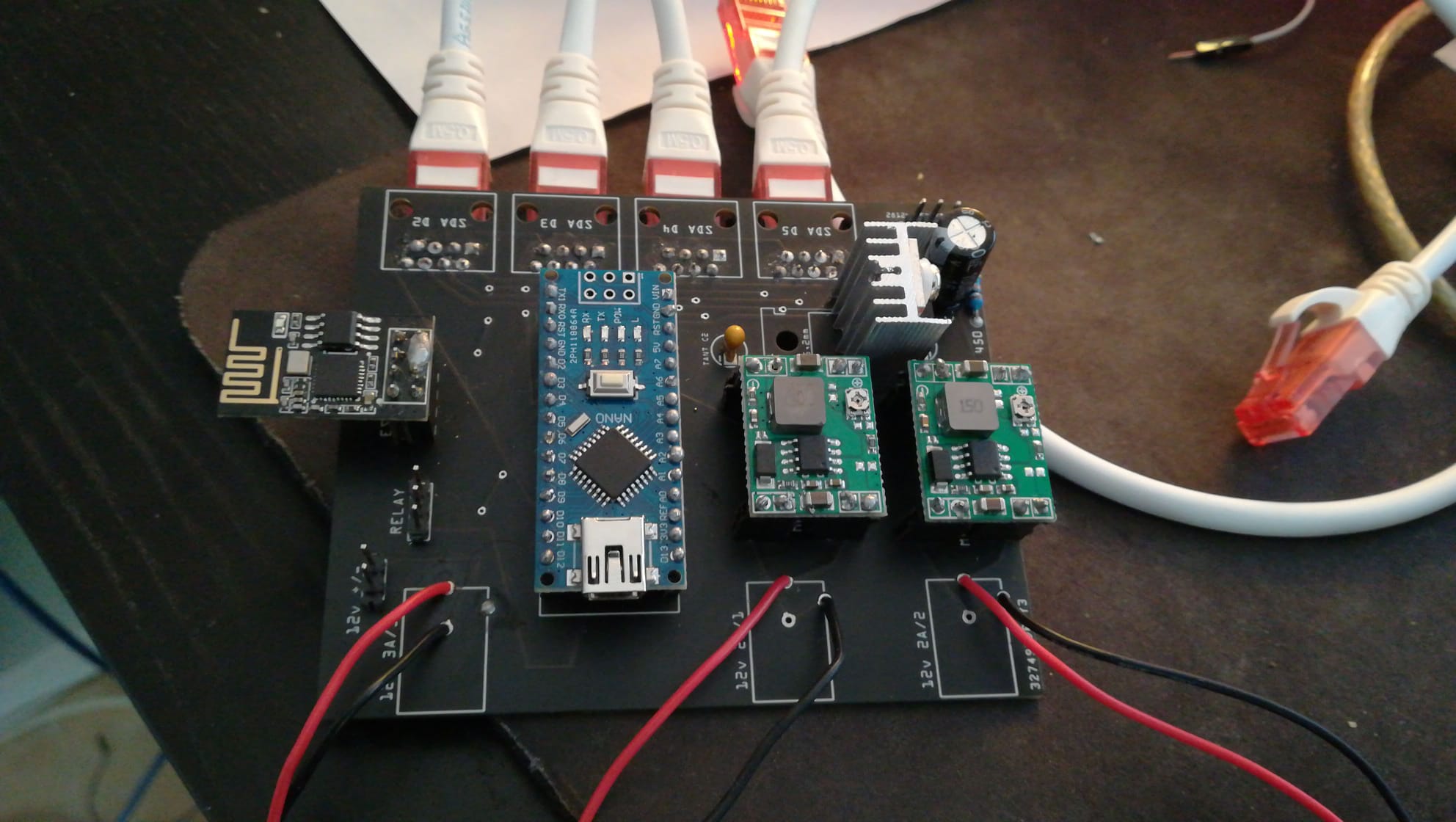
As you can see in the image, I had run into several problems:
First, the 2.1 Barrel Jack connectors didn’t fit with the PCB footprint created with Frizting, the 2.1 Jack has flat pins instead of regular ones so It doenst fit in the holes (My bad, I should have printed the PCB and try each component). As I’ll Be 3d printing a case for this PCB I dont mind wiring it up directly from PSU to PCB like the picture is showing so this problem is not really a big deal for me.
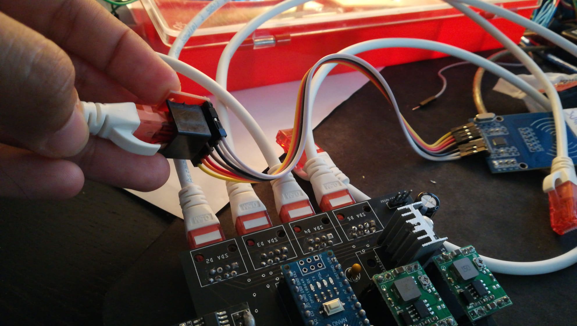
Second, the rj45 Connectors were flipped, so I had to solder them on the opposite side of the PCB to make them match the current pinout running trought the rj45 cable to the MFRC522.
Those were the mistakes I found on the PCB creation, as you can see, nothing that I couldn’t deal with.
Now the actual problem is that the circuit is not working as intended. MFRC522 Readers are not starting properly, not even a firmware error, they are just not recognized by arduino on Startup.
Checked both GND and VCC pins on the MFRC522 Side, steady 3,3v read by a multimeter. So voltage is not the problem I guess.
Checked continuinity between PCB and the actual MFRC522 pin, everything was OK. (Ohmetter between pin D2 and SDA2(on the MFRC522 PIN) showed up 1Ohm resistor so I guess this is generated by the cable itself and the components. The same happens with SCK(pin 13), MISO(pin 11) and MOSI (pin 12). Reset pin(pin 8) also shows continuity aswell as GND and VCC.
I’m powering up this project with 3 Diffrent wallmart: 2 of them are 12v 2A and one of them (for a solenoid lock) 12v 3A. One of the 12v 2A PSU is connected directly to the MP1584EN voltage regulator with an ouput voltage of steady 5v, this is wired to Arduino 5v Pin and LM1117T voltage regulator (that supplies 3,3v to ESP8266 and the 4 MFRC522 readers). The second 12v 2A PSU is also wired to a second MP1584EN Voltage regulator, 5V out for powering up a led strip (Wich works perfectly).
What I found strange was the fact that if I plug the Arduino Nano to an USB port its 5v pin will feed the LM11117T regulator and it will also give me 3,3v to the ESP8266 and RFID readers, also I can read 4,3v on the MP1585EN output hooked up to the arduino 5v. I guess this makes sense since arduino is triying to feed the voltage regulator in the opposite direction.
I shall say that this project was already created on breadboard and it worked like a charm, with same rj45 connectors and cables, the whole point on moving to PCB was avoiding the noises generated by LOT of dupont cables running from BB to the MFRC522 readers. So I don’t really have a clue why this is not working at all.
The video I followed months ago when I started the project was this : https://www.youtube.com/watch?v=f_f_5cL0Pd0&ab_channel=PlayfulTechnology
Not taking the codification in count (which i Know it is well coded since It was working on BB) do you think the PCB wiring is correct?
Sorry for the big post, but i Tought it was a nice idea to give feedback about this project and also to give you more information regarding this problem which is driving me mad already.
Thanks in advance guys for your help. Attaching the PCB Fritzing project if you want to double check it.heimdallRunes.fzz (123.7 KB)
Edit: I forgot to mention that ATMEGA chip on the Arduino Nano is getting hotter than I expected.
Hi guys,
Just to let you know that after several days triying out stuff I just decided to re-solder everything and suddenly it works. Seems like when you play with MFRC522 everything have to be perfect to avoid any kind of noise signals.
Thanks guys for your hard help on this, at the moment it doens’t seem to have any problems but I’ll keep you updated, this PCB was totally on you guys.
By the way, Does someone actually knows a better way to plug in the project without the 2.1jacks barrels?