Assuming the parts are wired up as shown on the schematic view, I do not see anything to cause the symptoms you describe. Try putting an ammeter inline on the plus side of the regulator board output. Either one at a time or both at once, to see what that actual current draw is. Or on the input side, to see what is being pulled from the 9V PSUs.
Your breadboard view is not wired very well. All but the 5V power and (one) ground wires to the nano are shown connecting directly to the pin on the nano. Connecting to the pins on the breadboard itself is more usual, and matches the normal way to breadboard the circuit.
Connections are not made in the breadboard view by ending a wire on top of the middle of another wire. The wires are insulated, and only make a circuit connection at the ends and bend points. That is why the ends of the many of the wires, and what looks like (but is not) a connection between wires are shown as red. They are not connected to anything. That is also why there are multiple ratsnest lines (dashed lines) between the RJ45 connectors. They are not actually connected together in the breadboard view, but because they are connected in the schematic (and pcb) views, the breadboard view shows where it expects a wire.
Temporarily moving one of the middle RJ45 connectors up or down will make those more visible. Moving the part like that also shows that only the yellow wire is actually connected to the rest of the circuit. The yellow wire ‘stretches’ to maintain the connection. The rest ‘move’, because the second end is not connected to anything where they visually end. The left end RJ45 also has the red, black, green, purple, and blue wires connected properly. The right end RJ45 also has the white wire connected properly.
The breadboard view should have wires in (exactly, or very close to) the same places as your physical breadboard project, even if the routing is different. Ending at a part pin, or on the breadboard as appropriate.
To help with breadboarding ESP01 (and similar) boards, I created a (physical and Fritzing) part to use as an adapter. I created several versions using different resources. First was a pair of long lead 0.1in headers, with carefully bent legs, then using a couple of 2x3 long pin headers, and finally using a 2x4 90° header. Here is a 2x3 version of the Fritzing part. 2 are needed to connect the ESP01 to a breadboard.
2x3_100mil_header_to_300mil_dip_adapter.fzpz (3.3 KB)
An older 2x10 version was previously posted in Part Submit. Here it is again.
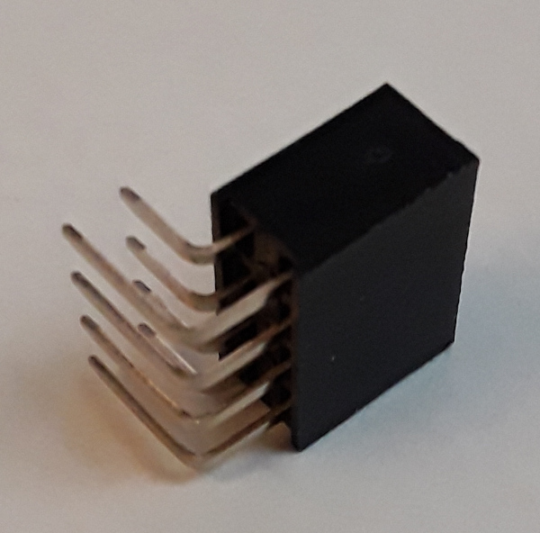
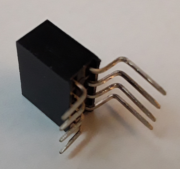
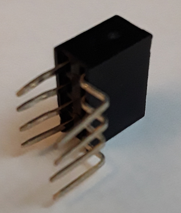
And an image series of the progression creating the physical part from a 90 degree header.
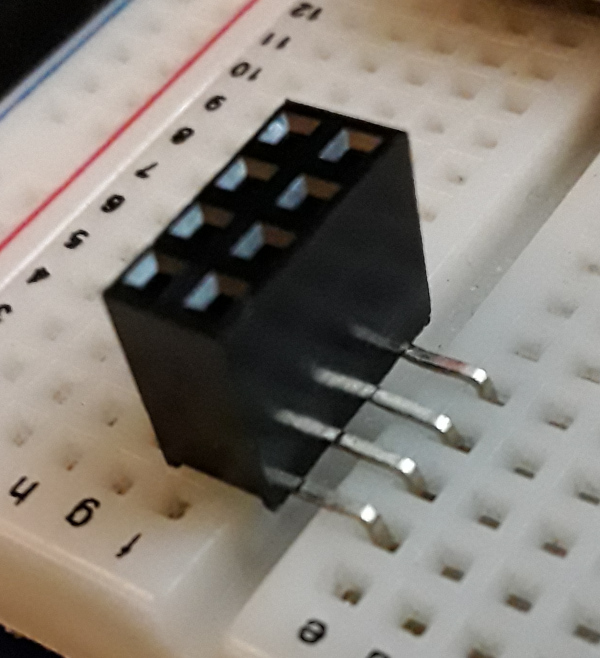
Using something like that make the breadboard (both physical and in Fritzing) much cleaner.