Top & bottom layers we have! You can fully layout them, not sure what you’re missing here?
Editing number of connectors: can you be a bit more specific, or provide a screenshot?
Btw, I also moved this post to the “wishlist” category. Alternatively, if it’s a more detailed and concrete improvement suggestion, the github issue tracker would also be a good place.
Thanks Andre, Sorry the ‘error’ was is in Parts Editor again …
When loading a .svg file into parts editor for PCB view, with new parts that I’ve drawn up, it doesn’t recognise them correctly - the error message returns :
It only accepts one layer & there are errors with copper layers top & bottom not linking + I get the dreaded ‘Red Square’ in centre. I’m using version 0.9.2b.32.pc . I haven’t used previous versions, so don’t know if that helps …
As to the number of connectors in the ‘view’ tab, the actual number of connectors can be stated, but when it comes to larger numbers ( like 200-300 ) it can be difficult to move / edit / delete the id: number ( especially if you get them in wrong order or try to edit / delete one in the middle of the stack )
I hope that clarifies the situation – I might try & get some screen shots later if that helps …
When making parts you need to properly name the copper0 and copper1 grouping, also grouping order is important. I suggest you open a known working .SVG file for another included fritzing part. Look @ the grouping on that said part. Then replicate that naming process within your part.
This will happen if fritzing sees and .svg file it doesn’t recognize as useful.
I am aware of the correct naming procedure & followed the directions listed on the site ( link to go here later ), I may however have stuffed up on the grouping order though …
Can anyone confirm which order they are supposed to be in ?
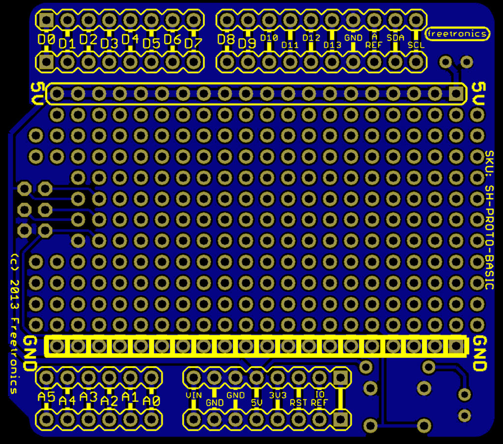
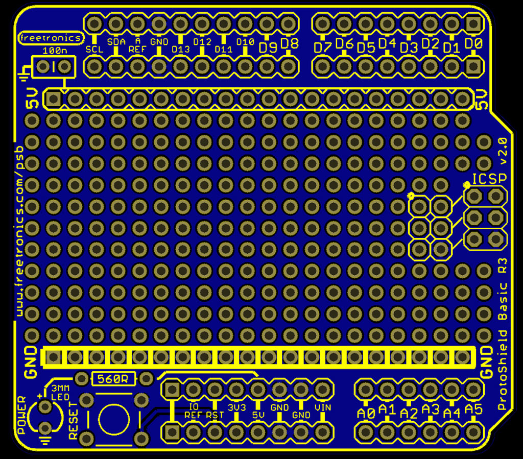
I do have another project ( which is a bit more complicated ) that I’m currently working on, a proto shield basic with a single layer on both sides - I do have trouble with, as it has over 300 pin holes & fritzing doesn’t like it … ( haven’t loaded it on here yet as there are way to many errors in it ) these are the top & bottom layers ;
As you can see there are a lot of pin holes, and is bit of a nightmare trying to get them all to work.
& for those interested, here is the .svg file ; ( Doh … can’t load a .svg on here … ? )
I noted that at times when importing files, some elements were hidden & can’t be seen in Illustrator but layers are there, wondering if that has something to do with errors appearing in fritzing …
Hoping to get it working so I can move on to the next project …