In the circuit shown in attached Fritzing file, the Bread Board Window and Schematic Window displays the circuit correctly. However in the PCB Window, there is no ground trace connected to the upper right pin of the MakerFocus 30102 Module. In the other two windows, this ground connection is shown as a black wire. How can I get Fritzing to add the Ground trace in the PCB Window?
The ground pins on the 20102 part are bused, and therefore since there is a connection to one of the ground pins, the internal connection is making the ground connection. In order to make an actual connection (which if the grounds are connected internally isn’t needed) you would need to manually connect a trace between the two ground pins like this:
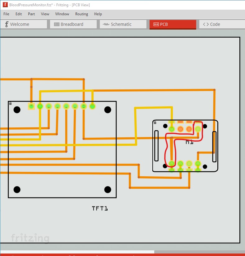
Here I selected the left ground pin and dragged a trace to the right ground pin. The correct thing to do however is use an ohmeter to check if the two ground pins are connected internally. If they are not, then the part is wrong and you need the trace, if they are connected then the part is correct and you don’t want the added trace as it adds a second path to ground which is incorrect.
This is a subtle point. I knew that the ground pins were tied together. I tried dragging a trace from the upper right pin down to the lower left pin. That didn’t work. Murphy’s Law!
Thank you for your solution.