As I get towards the end of syncing by breadboard and schematic views, so I can move on the PCB, I encounter this problem. There will be a few rats nest connections appearing on the schematic that shouldn’t be there. So I delete them, or try to, from the schematic. Then when I go back to the breadboard screen to look for them, affected parts have moved themselves off the board, leaving trails of blue wires to their original location.
I tried locking those parts, but they still move. And when they move, that creates new connections which break my project. It mainly happens to big multi-pin parts, like ICs and headers. Last night I spent about an hour entering a schematic and doing rough perfboard placement. But once it was nearly complete, I spend nearly two hours playing wack-a-mole with other spontaneous connections before I gave up. Often the part that would move would be the power header, and it would cause the power and ground leads to connect, creating nonsensical rats nests for the entire board.
This is with fritzing-0.9.3b.linux.AMD64 under KDE Neon 5.12.5, an Ubuntu 16.04 variant.
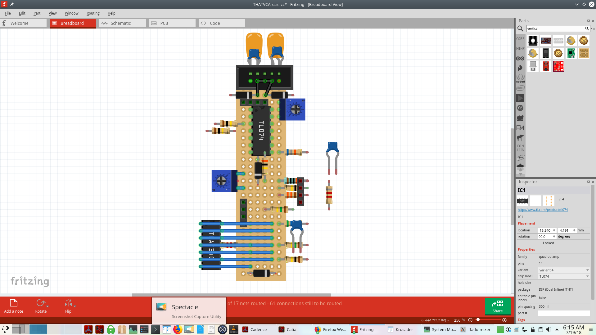
Since I can upload only one image, here’s the “after” picture, where the left trimpot and bottom IC have moved. The other parts near the edge are deliberate, to indicate vertical mounting.
You are modifying the circuit in one view while there are SOLID connections to that part in another view.
Lest hope you haven’t broken the sketch, but select the part you are having trouble with and delete all connections to it in all view until you only have ratsnests. Delete extra rats you don’t need. Start connecting the part with solid connections in the view you are working on, and trust the rats in the others.
Yes, but doing so seems necessary to keep track of all the parts and placements. There doesn’t seem to be any way to search for and highlight one particular part or connection. Even connecting a resistor backwards puts the views out of sync with each other.
…select the part you are having trouble with and delete all connections to it in all view until you only have ratsnests. Delete extra rats you don’t need. Start connecting the part with solid connections in the view you are working on, and trust the rats in the others.
That’s precisely what I have been doing. But it never stops. The environment is clumsy enough without deliberate move/connect tools - but I have parts moving and connecting by themselves. My method is to always start with the schematic and treat that as the authoritative version. All I have “modified” on the breadboard view is gradually making the same connections that already exist on the schematic. What I need is a way to prevent ANY automatic connections, and ANY parts from moving. Why doesn’t the lock function work? Why are parts becoming wired to the perfboard when those connections were never specified anywhere?
Resistors and other parts have numbered pins. Hover over the pins and you will see pin 0 and the opposite is pin 1. What you are probably doing is connecting to pin1 in one view and forcing that connection to pin0 in another.
Go to BB and PCB and select all traces, and then delete. Go to SCH and delete all wrong rats and finish SCH. Now go to BB and trust the rats and start connecting. The trick with reconnecting parts is you click on the part pin and everything that will be connected to it will turn yellow, and that gives you the guide where to run the trace.
Linked views is brilliant, you just have to know the tricks. If you like you can try another EDA, because they don’t link views so you can’t make that mistake, it’s just you have to do everything twice.
If you can’t work it out post the ,fzz with the 7th button and I’ll look at it.
It would be most useful for you to upload the entire sketch (the .fzz file) which would let us access the actual sketch and see what the problems are. Single view screen shots are rarely useful.
Normally placement of parts does not change from view to view i.e. changing something in schematic will not change placement of part in breadboard, only connections at the rats nest level not placement of the parts. As noted changing solid lines in one view to something that conflicts with a solid connection in another view will cause problems though.
Click on any pin (in any view) and everything that connects to that net will be highlighted in yellow (and if you have pins that should be connected but aren’t highlighted then there is a connection problem in this view).
Yes, because component pins are part of a net (which is where rats nest lines come in) and if you reverse them in another view they will reflect (and cause misconnections due to shorted nets and potentially corrupt the database) in the other two views. That’s why the recommendation is to do one view completely then follow the rats nest lines when making connections in the other views.
This part is abnormal. In the breadboard view displayed above the parts are not placed correctly (they won’t connect like that on a real perf board.) The first step in breadboard should be to position the components in the correct physical position and preferably lock them so they don’t move then make the connections according to the rats nest lines (rotating components if required if the rats nest lines show they alignment is backwards.) Note perf board as you have selected is one connection per hole so the wires on the bottom IC connect to nothing (the perf board itself will accept a connection, but it connects to nothing in schematic as it has no representation there.) you may want strip board instead. There are no rats nest lines showing indicating either they are suppressed in breadboard view (which is not the default) or schematic isn’t done. Without the full sketch I can’t say much else about this.
There is actually a safety built into FZ where if you do something in another view the part will jump off the BB with solid wires to it, telling you something has changed. Too bad it doesn’t have that in PCB.
I think I submitted it as a bug - maybe bendable leg part moving - , but now I think it tells you something changed. I think BB is a solid connection so the part has to move, the only problem is that it takes a lot of wire deleting to get an IC back to the BB.
I can appreciate that as a novice user, there would be some concerns about my technique. I probably should have stated the problem more succinctly. After all, I posted it under “bugs” rather than “tips” or such.
To simplify and focus my initial post:
Regardless of my ability to make the proper connections - are changed connections in one view supposed to physically move those parts in another view?
Are parts that move supposed to change their connections according to their new placement? For example, if I were in BB to intentionally drag or rotate a resistor so that its lead touches that of another resistor, are they then connected in the netlist, or only if I explicitly indicate this by running a wire?
Were just saying that you have use the FZ method or it tangles up the views.
Yes in BB - I can’t remember if PCB moves parts -. I think you might also have a problem with connections. If the part pin end isn’t green it’s not connected, that doesn’t mean to say it’s not connected to something else somewhere else. Clicking on a pin turns all connected and bendpoints along the way to yellow.
Depends if you have a solid connection in another view. This looks like another connection problem, and the thing about connections is they are not connected if touching, you have to purposely make a connection.
Load the .fzz here with the 7th button and we will give you pointers so you can learn.
While I would have said no, it appears I am wrong. It appears there is some condition (which I can’t reproduce so far) that does this if you make a mistake. I tried a simple meaningless circuit and reversed the direction of the resistors in breadboard, but it doesn’t appear to move the IC as you are seeing. So if as Old_Grey suggested, you upload the .fzz file of your sketch one of us will have a look at it and see if we can figure out what is going on.
This is the sketch I created, but it doesn’t move the IC but rather indicates the resistors are shorted with a rats nest line as I would expect because the resistors are oriented backwards between breadboard and schematic.
It depends on the view and where you are moving. In breadboard, if you move something on to the breadboard it will connect to the breadboard and thus to what ever other connections are on that row of connections which can do unexpected things. Otherwise (AFAIK) you need to connect the two pins with a wire. In schematic, sometimes dragging a wire across another connection will make a connection that you don’t want and you need to use delete wire to bend point or delete wire to connect it (I find this very annoying!).
Gee I can’t reproduce it now. I think it was the LEDs with bent legs on my Timing Light circuit, and I remember doing something and they popped off the BB.
I suspect CJ problem is more than forcing connections in another view, I think he might have things that look like they are connected but aren’t actually.
Someone could probably work out what’s happening in 3 min if we had the uploaded sketch, but when you don’t know the tricks you could spend hours and still not work it out.