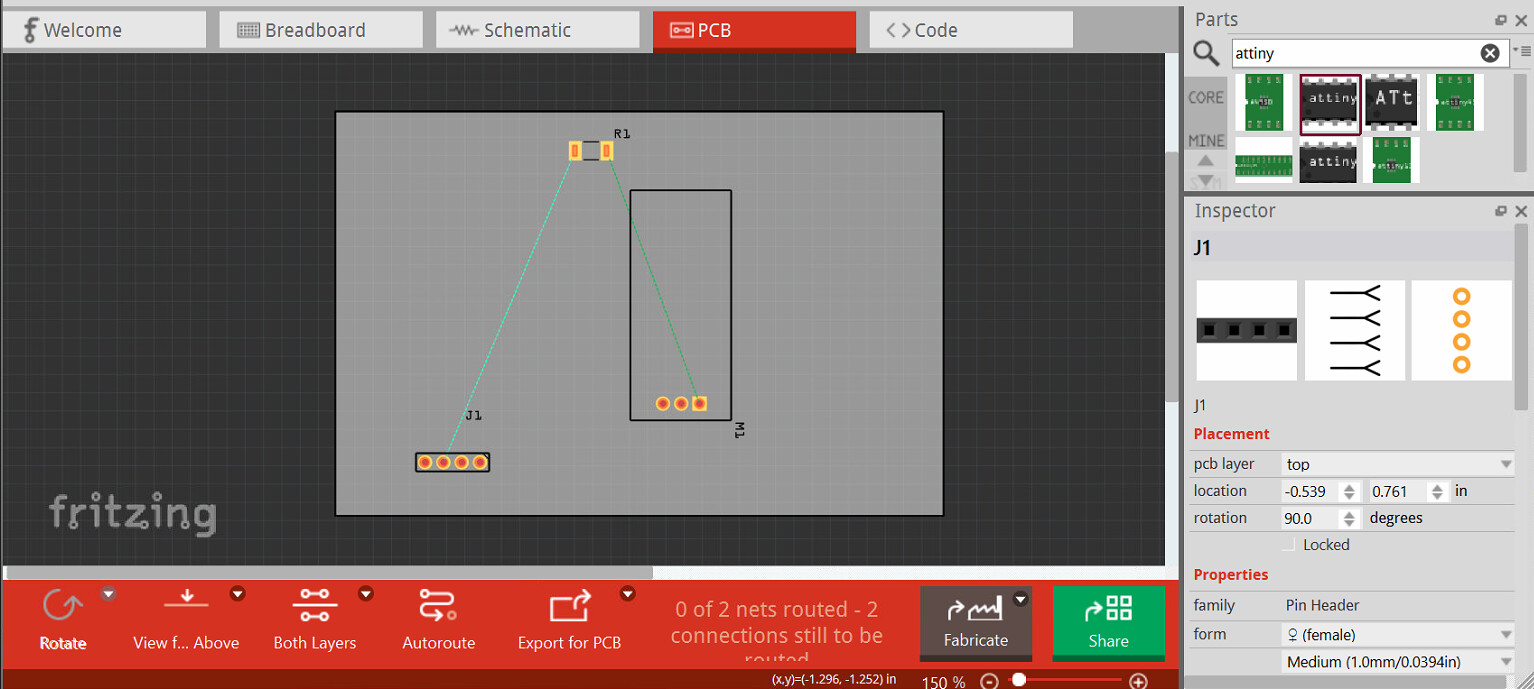
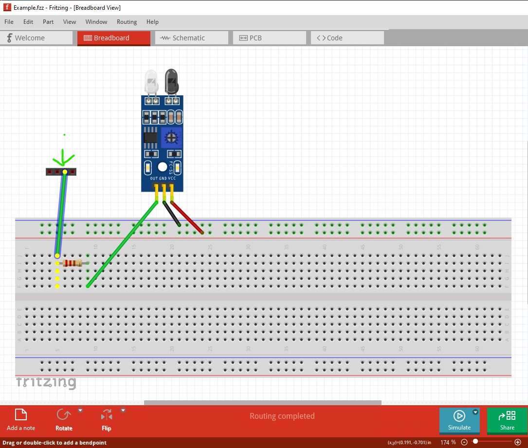
I don’t know what I am doing wrong. When I go to the PCB its like the parts are inverted. The parts are on the top layer and I am in View From Above. I just threw some stuff on a breadboard to provide an example. I connected pin 3 of a header to a resistor then to pin 1 of a sensor. In the pcb view it looks like its pin 2 to resistor then to pin 3. I know there are some ways to work around it like moving the parts to the bottom or rotating the headers but it just seems like I’m just doing something wrong. I’m a new user so it will only let me use 1 image. If you need to see the breadboard or the schematic view I will try to put it in a reply.
Upload a copy of the sketch (the .fzz file, do a File->save or File->save as which will let you change the file name if you haven’t saved the sketch.) Then upload the resulting .fzz file (upload is 7th icon from the left in the reply menu and will accept .fzz files as well as images.) The sketch will allow us to see what is going on (and if it happens to us or is something wrong in your system.)
Peter
Thank you.
Example.fzz (2.8 KB)
It isn’t anything you are doing wrong, the fc-51 part in core parts appears to be wrong as it doesn’t match breadboard but is inverted. Breadboard goes pin1 pin 2 pin 3 with the connector at the bottom like this:
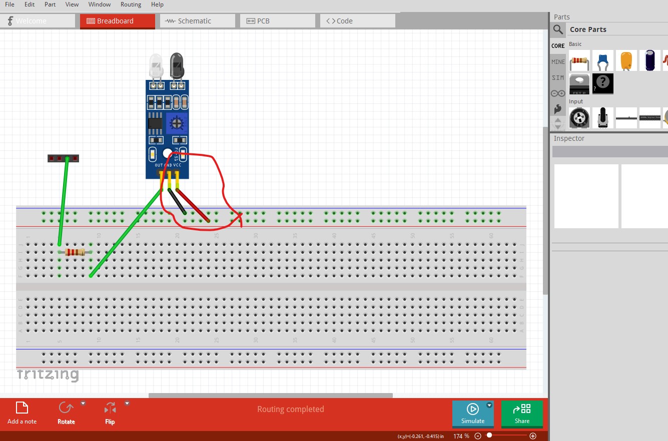
note that the power and ground leads from the fc-51 only connect to breadboard nothing else (it needs a power source part also connected to breadboard to work) and thus won’t show up as connected in the other two views. Schematic is correct as far as I can see (I routed it to make sure) Note the VCC and GND pins are not connected to anything because they are only connected to the breadboard which doesn’t create a connection unless there is another part also connected to the breadboard rail.
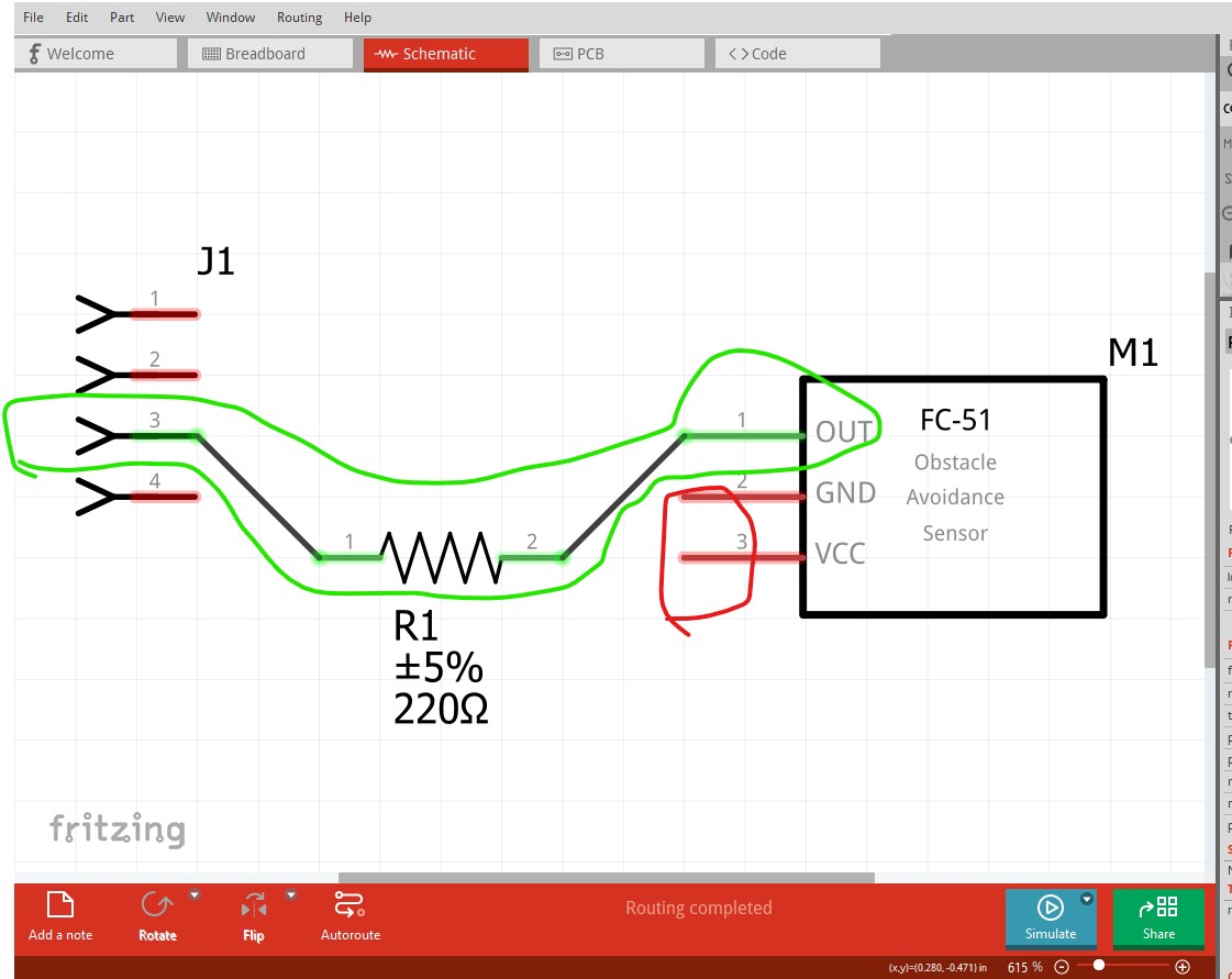
If you hover with the mouse over a pin Fritzing will bring up pin number information on the pin like this (in all three views!) which says the resistor is connected to pin 3 of the connector (which should match schematic and pcb which it does) note that connections reflect in to the other 2 views so if you route the resistor the way it is in breadboard but the opposite way in either schematic or pcb (which you can do!) the will create a short across the resistor (which will show up as a rats nest line shorting across the resistor although it can be hard to see, right clicking on a pin will make the short obvious!)
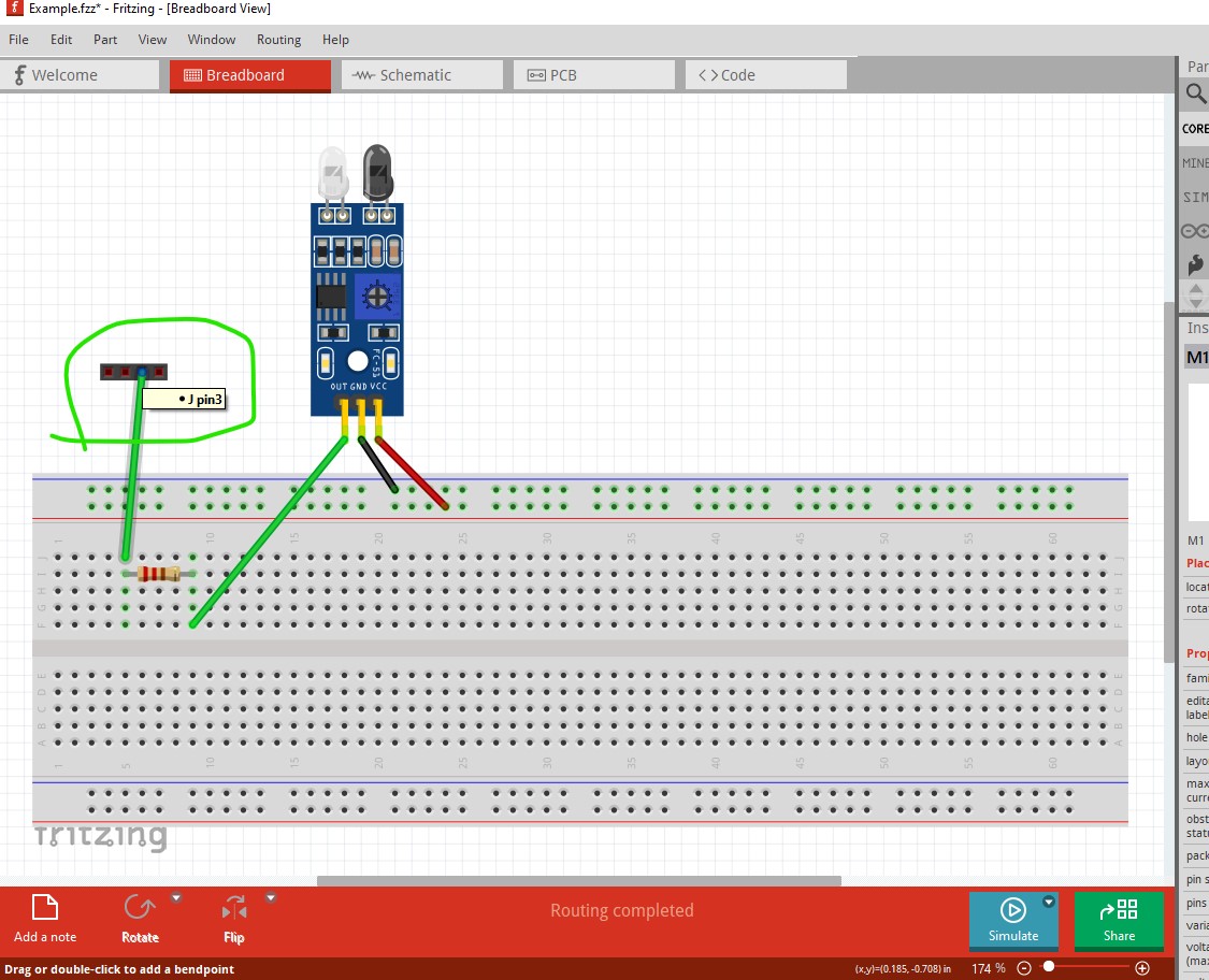
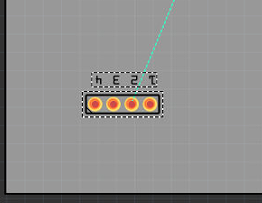
another useful trick is right click on a connector (here I right clicked on connecotr3 of the header)
That lights all pins connected to this net yellow indicating where connections may not have been made. Pcb indeed has a problem. The parts are oriented at random (in this case the header is backwards from breadboard but rotating it 180 degrees will correct that) but pin 3 connects to the SMD resistor (which only exists on the top of the board and thus will only route traces on the top layer) and the other end of the resistor goes to pin1 on the fc-51. Unfortunately the fc-51 part is incorrect and the pins are in the wrong order. Pin 1 should be on the other end (in the direction of the red arrow. ) It is possible to make a corrected part for the FC-51 if you want to use one but the one in core parts is wrong which is not anything you are doing wrong.

an unrelated tip: enable snap to grid like this (it is currently off)
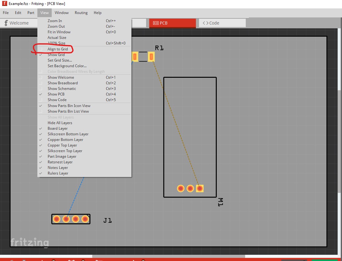

then move all the components in pcb a bit which will cause them to align to whatever the grid size is set for (by default 0.1in.) That makes aligning traces horizontal and vertical easier as the traces will also snap to the grid. You can change the grid size in View to any value you need. Hope this helps, reply if you need a fixed fc-51 part.
Peter
Wow! Thanks for the detailed reply. The mouse hover is going to help a
lot. Since I have to rotate the header to the correct orientation is there a way to rotate just the label so it matches up with the pins or should I just use text for this?
Also, yes I would love a fixed fixed fc-51 part. I’m to start a project with 20 of these soon. It would be very helpful.
Right click on the label itself (not the main part) should give a context menu that includes label rotate options.
Awesome, Thank you!!
OK here are two new parts that have been corrected. There are two because simulation was added and there is an off version and an on version for simulation. If you aren’t using the simulator either one will do. I corrected pcb and since I was there updated the part to meet the graphics standards. I’ll open a ticket on github and see if I can get core parts corrected (I suspect there may be problems with obsoleting so this may not happen!)
simulator in off state
fc-51-IR-Sensor.fzpz (14.7 KB)
simulator in on state
fc-51-IR-Sensor_On.fzpz (14.8 KB)
if you have sketches you want to keep a “delete minus” will delete the part but leave the traces. You can then load the new part and drag the end of the wire on to each connection in each view to reconnect it.
Peter
Thank you for all your help!
@KjellM said that the PCB could be improved to remove the gold square and add a “+” text in Silkscreen to help users identify the VCC connector when mounting boards
Hence, here are the updated parts
fc-51_ON_improved.fzpz (26.3 KB)
fc-51_improved.fzpz (26.3 KB)
@vanepp all fine right?
Yep looks fine.
Peter
1 Like
Good news everyone!
The fc-51 has been fixed with no errors
Hope @KjellM will integrate this into Fritzing