Welcome aboard! Translates are the root of all evil . There are translates in schematic (which usually are not a worry) but in this case they are breaking things. A number of other changes as well:
breadboard:
rescale to the preferred scale
pcb
change pad stroke width to 20 (20 thou) and radius to 25. to give a 0.030in hole (suitable for swiss type pins.) For .1 header pins change the radius to 29 (a 0.038in hole.) Added a rectangle and pin 1 marker in silkscreen layer and a square on pin 1 in the copper layers.
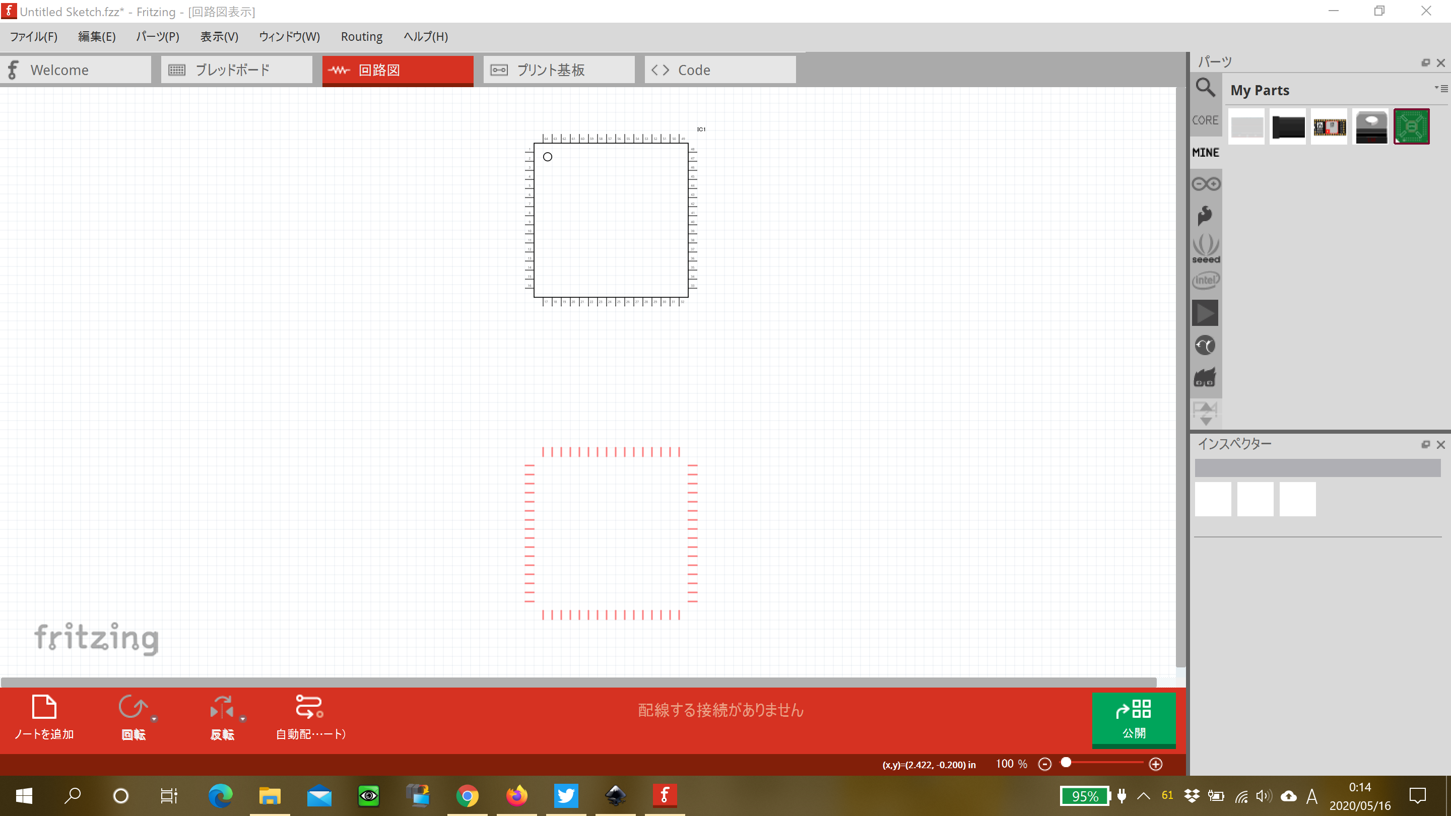
schematic:
ungrouped to remove transforms. Rescaled. Replaced path for pin numbers with text to make changes easier. Replaced terminalId circles with 10 thou 10 thou invisible rectangles, change the paths on pins to lines. The translate removal was the cause of the problems, the rest convert it to a more standard part.
I didn’t change the file names so you will need to delete your current part (and probably close Fritzing to complete the deletion) before it will let you load this one. If you have sketches already, a delete minus will delete the part but leave the traces. When the new part is installed dragging the end of a trace on to the new part will reconnect it.
These two tutorials may help (if you haven’t seen them) as well. They both apply to the current version of Fritzing (although I avoid parts editor mostly) where most of the others are for older versions. Always happy to help people making parts , the more the better.
 , the more the better.