I want to create a PCB Layout, which is connected to several external parts (NTP to measure temperature away from the PCB, external Power Source).
What is the correct workflow?
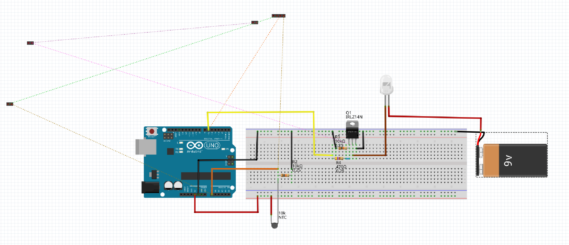
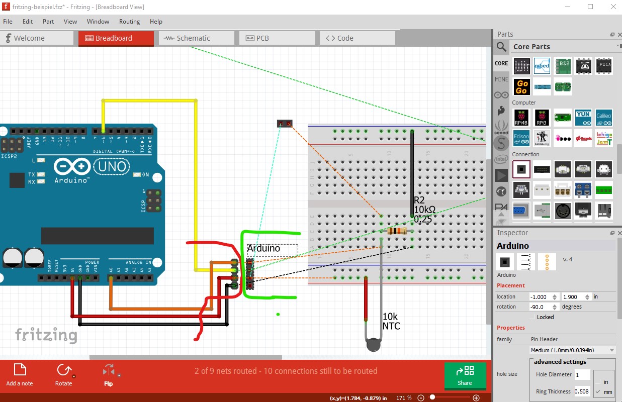
Breadboard view:
No problem here, i can connect all the parts. When I add Pin headers to the PCB to connect the external parts, they appear here as well.
Schematics:
At first I can connect everything, but when I add Pin Headers to the PCB, they appear here and are unconnected.
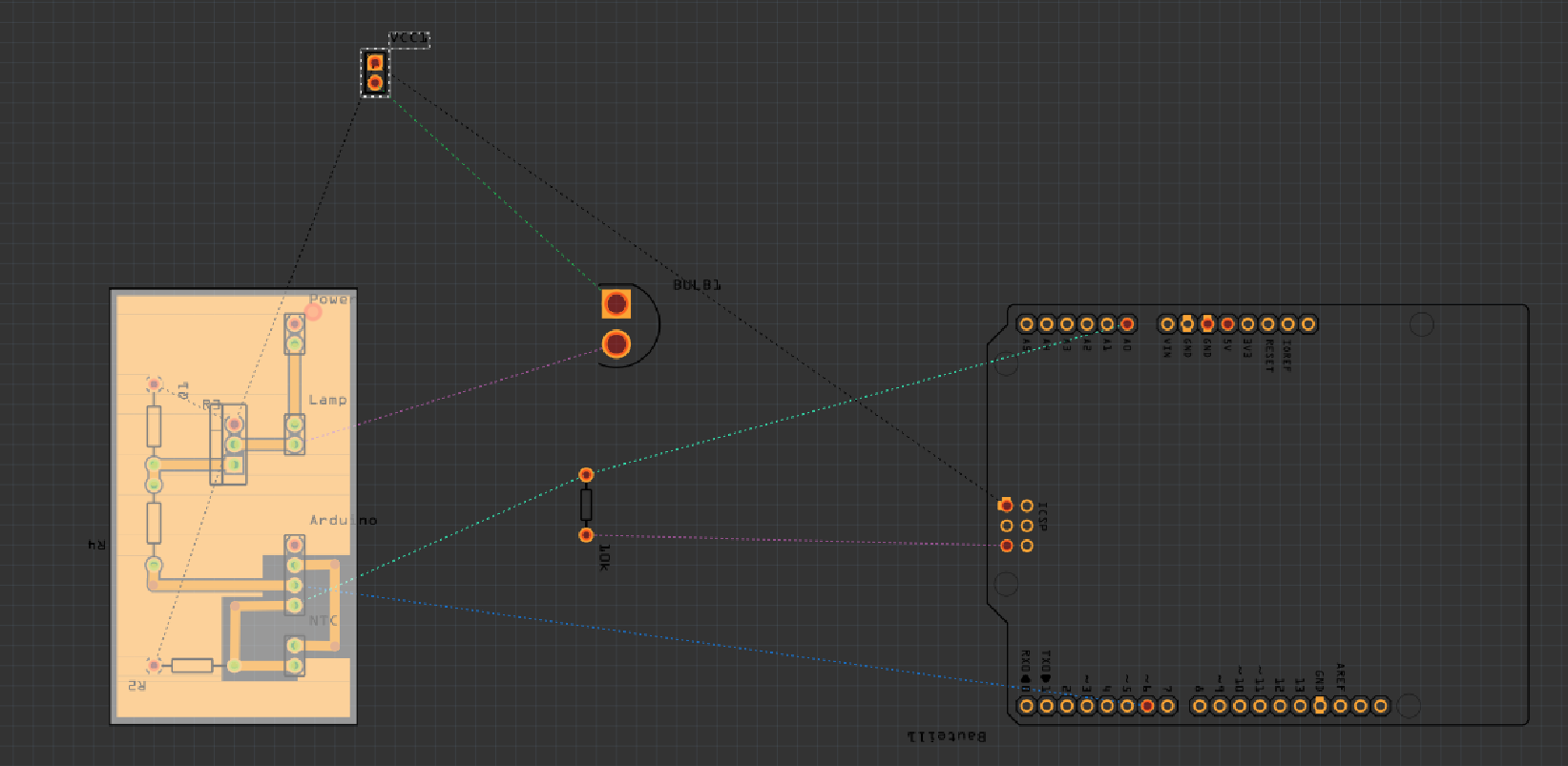
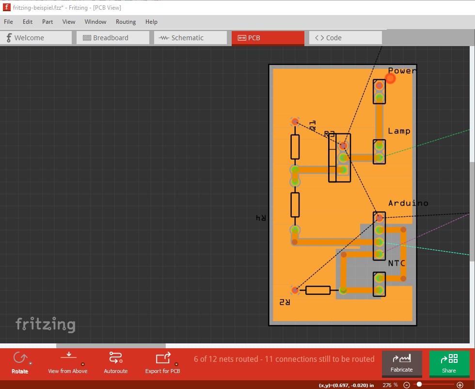
PCB:
I add Pin headers to connect the external Parts. Now I am unsure if i have to connect the air wires, as I do not want to mill them. They should be physical wires to an external part.
In the end, I have a working PCB design, which I can mill, but it is rather unsettling, that there are the unconnected Pinheaders in the Breadboard and schematics view and the air wires in the PCB View.
I guess my workflow isn’t quite as intended. Maybe someone could help me out!
You need to connect wires between the place on the board where the NTP should connect via the pin header to the pin header (which it sounds like what is missing.) It is however impossible to say from an explanation. Your best bet is to upload the sketch file (the .fzz file, upload is 7th icon from the left in the reply menu) so we can see the sketch and comment on problems and solutions.
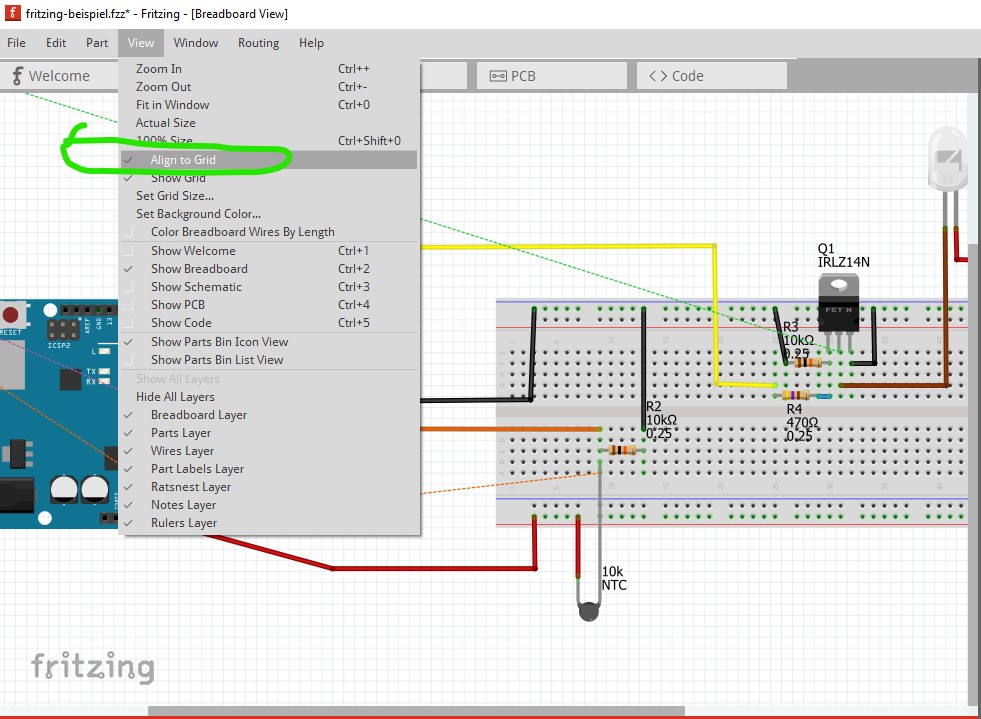
I think I see your problem. But first some appearance tips: set align to grid in all three views (it is currently off) so parts will snap to the 0.1in grid. To do so click on View->align to grid to enable it. Then you need to move each part so it snaps to the grid. At that point the wires will align to the grid which makes it easier to see what is happening.
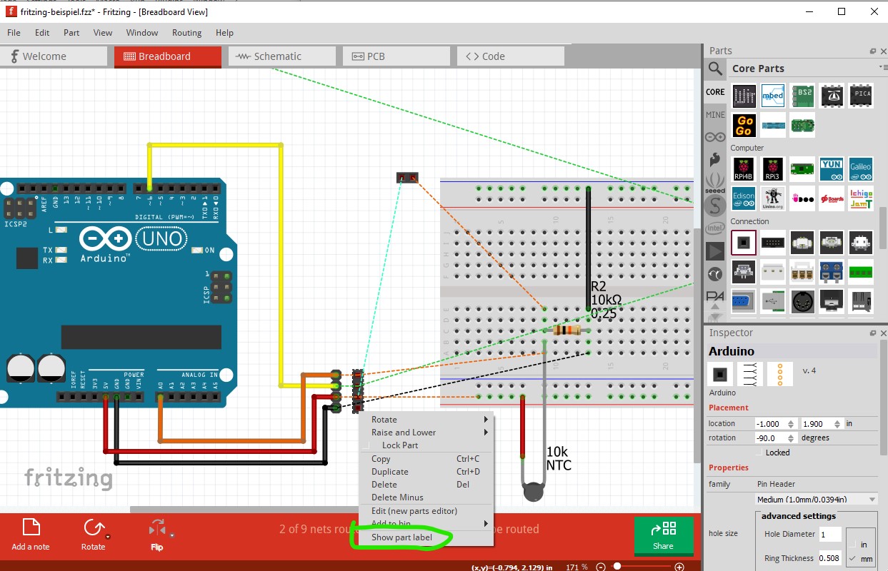
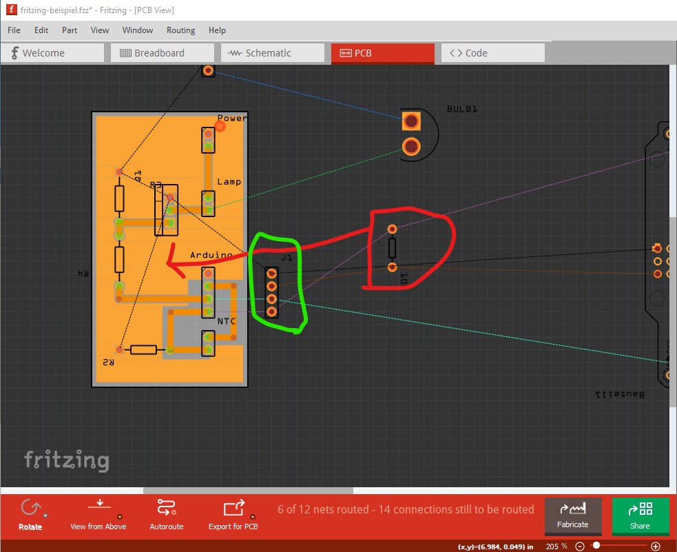
Now on to what I think is wrong here: you don’t have sufficient connectors! The purpose of the headers on the pcb is to connect to the Arduino, bulb and battery off the pcb. To do that you need a male and female connector. However first I enabled the part label on the header so I can see which one is the Arduino like this:
Since the one on the board is female, here I added a 4 pin male header for the Arduino then connected the wires to it in the order they appear on the female connector for the board
Note the arduino female header now has the part label Arduino to tell us what it is. The male header (behind the red line) connects to the Arduino. The female header (on the pcb) should connect to the circuitry that will be on the board, but at present does not because there are connections directly to the Arduino in schematic and pcb view which reflect as rats nest lines (the dotted colored lines) indicating a connection in another view. You need to connect all the traces that will be on the pcb to the female header. When you do that there will no longer be any connections to the Arduino, but once that is done if you route a wire between each pin of the male header and the female connector the connections will then appear in schematic and pcb. It looks to me like some of the connections are incorrect, as not all the pins that should have connections do. As well I think the resistor (circled in red) should be on the pcb not off of it.My new connector for the Arduino is circled in green. Note the Arduino female header does not have a ground connection! You can see in breadboard the last connector does not connect to anything.
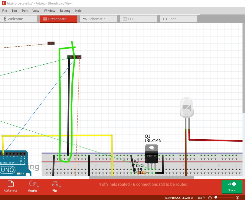
Everything outside of the board area will not appear on the pcb (which is presumably your desire) but will appear on schematic and in breadboard. Only parts inside the boundaries of the pcb will appear on the pcb. Hope this helps!
My mistake! I assumed the bulb was the Thermistor and thus that was the resistor not the thermistor.
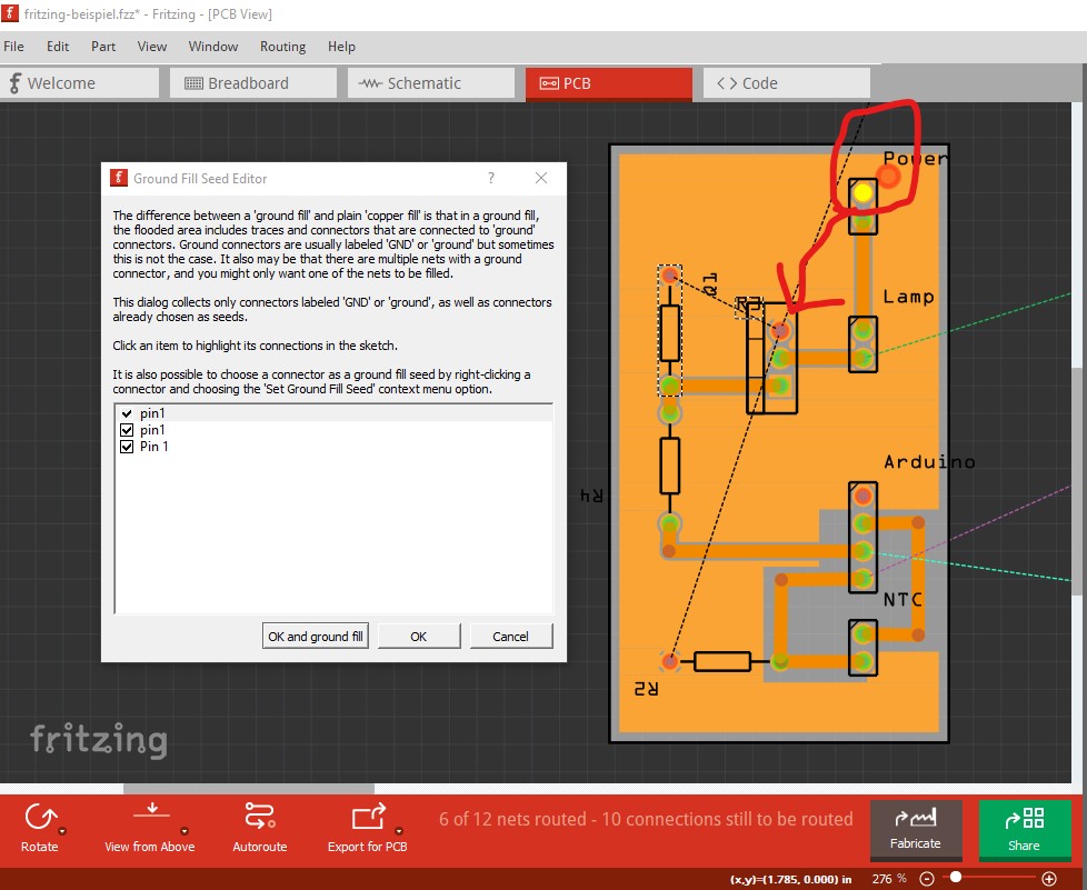
There are bugs in the ground fill code, but I don’t think that is what is happening here (although it may be!) I know almost nothing about ground fill (but was helping someone else with ground fill problems) but I believe that the two extra ground seeds should be connected to the ground net and they are not. This is the main ground net
when I click on the bottom ground seed selection all the connections in the net should light yellow (this is true in all views, left clicking on a connection should light all pins connected by the net yellow.) Here that isn’t happening to the two alternate ground seeds (although I expect it should be, as adding them as ground seeds should add them to the ground net.) That is the reason there are no rats nest lines to the pins in schematic and breadboard and I think it is likely a bug. If I select the other two ground seeds
In both the above images there should be a rats nest line along the red arrow to the ground net as they are all connected via copper and thus part of the same net. Connecting the pin header in breadboard to ground should fix this: