I have this part from Adafruit LTR303 ( Adafruit LTR-303 Light Sensor - STEMMA QT / Qwiic : ID 5610 : $4.50 : Adafruit Industries, Unique & fun DIY electronics and kits
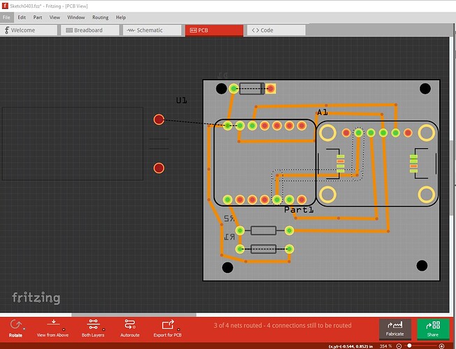
After making Breadboard and schematic for it using the standard pins on the LTR303 board, the PCB does not use the pin but instead use the STEMMA QT in the routing connections.
I am new at Fritzing and need some help to redirect the connections on the breadboard.
If you have made connections in one view (such as breadboard) they will appear as rats nest lines in the other 2 views. Due to a bug in Fritzing, it is recommended to complete on view (such as breadboard) completely then switch to the other two views and click on the rats nest lines to make the connections. Making connections in another view (especially incorrect ones!) can lead to problems.
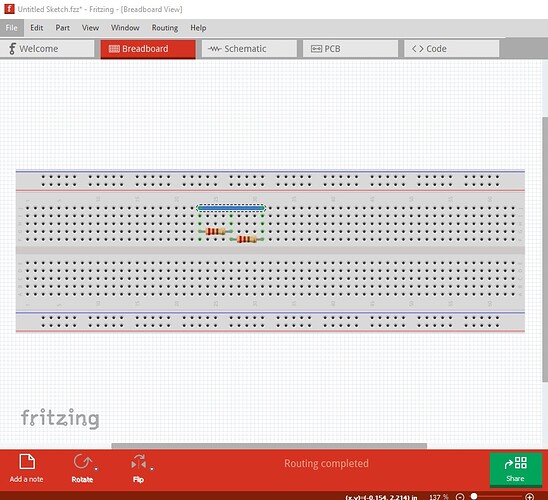
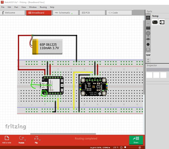
Making the connections in breadboard
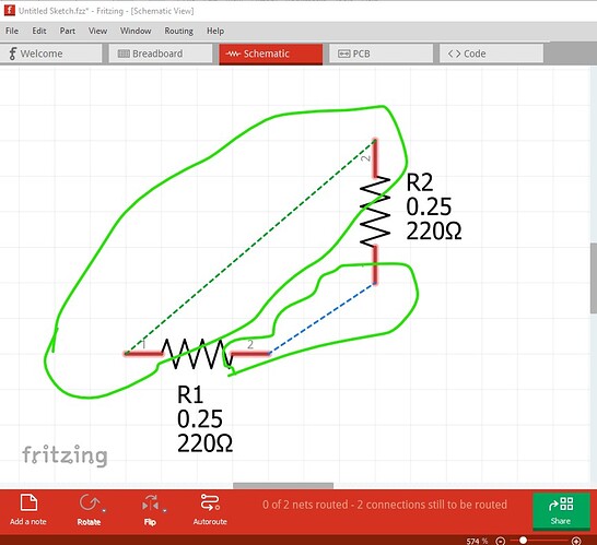
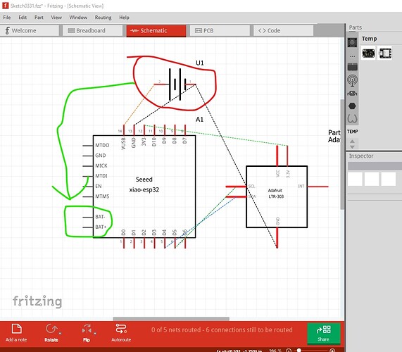
turns in to rats nest lines in schematic
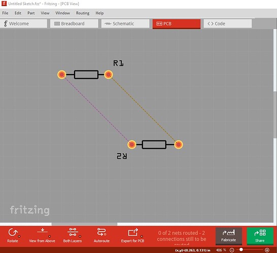
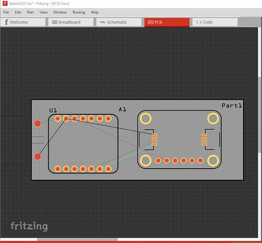
and pcb
clicking on the rats nest lines will create a wire. That said your best bet is likely to upload your sketch so we can see what you are doing and what is wrong. To save the sketch use file->save as which creates a .fzz file of the sketch. then upload the .fzz file here (upload is 7th icon from the left in the reply menu.)
Peter
OK I think I see your problem, which is a Fritzing oddness. Breadboard has a few issues but is over all fine.
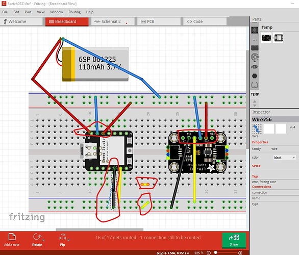
The connections direct to the pins will work but not in real life on a breadboard so it is preferable to move them to breadboard pins as in real life. The two yellow wires don’t connect to anything and the ground wire on the bottom isn’t connected to the ground rail (you can tell because there is a rats nest line indicating a connection in another view in parallel with the wire. Also the Xiao isn’t aligned correctly to the breadboard (it is off by about 0.05in.) Here is how I would correct breadboard
I moved the Xiao a bit to the left til it snapped to the grid then connected the wires to the breadboard pins rather than the parts pins (as noted either works in Fritzing though.)
Schematic shows a potential error, as I recall from the Xiao schematic (I made the Xiao part) the battery connects to two of the pads on the bottom of the board which are shown in breadboard but not in pcb on the THT part.
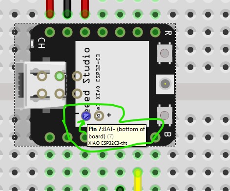
As I recall the VUSB input pin is connected to 5V from the USB connector and I don’t think it is intended for a battery, you can either solder wires to the SMD pads on the bottom of the board (likely the easiest) or switch to the Xiao-smd part which makes it entirely SMD (which will likely be hard to hand solder as the pads are under the board!) I expect that there is a charger circuit on board that will change the LIPO battery from the USB connector (and probably boosts the LIPO battery to 5V as well.) PCB is I think your main problem though and that is a Fritzing oddness.
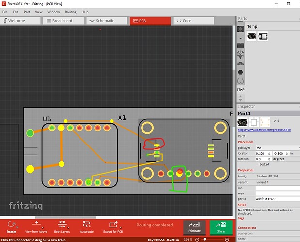
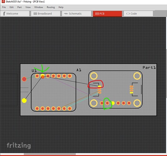
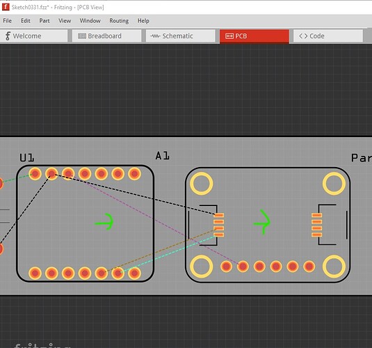
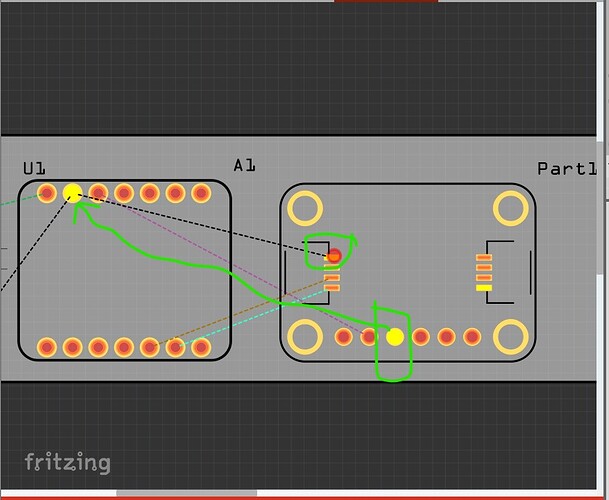
Here I clicked on the pin circled in green which lights all connections to that pin. As you see (and I expect the source of confusion) there is an internal connection between the THT pad (that I clicked on) and the two SMD connectors. The rats nest line (here I deleted all traces in pcb) will route to the closest physical connection to the same net like this
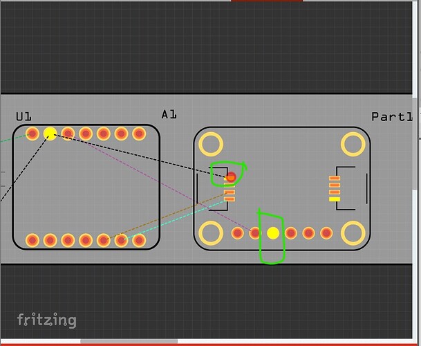
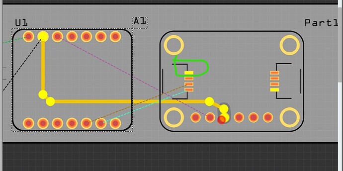
However you can route the connection to any other connection on the part (in this case I would use the THT pads) like this. By clicking on the pin you want to connect, Fritzing will light up all the available connect points in yellow like this
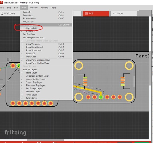
first I would enable snap to grid by ticking this box
which changes to this and snaps the parts (when moved!) to the grid
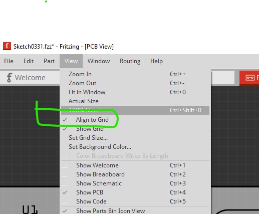
then move both parts slightly to cause the to snap to the grid
then what I would do is manually route the connection to the THT pin like this
first click on the SMD end of the rats nest line which lights the alternate through hole connection yellow then route the trace from the through hole connection instead of the SMD one like this
which results in this where the SMD connection still shows as a possible connection, but the actual trace is to the THT pad which is easier to solder.
Hope this helps and answers your question, if not please post again!
Peter
Thanks Peter, Your input is very helpful as it is my first board with Fritzing. For some reason I was not able to remove one connection to the stemma but I think it’s OK. Now I want to use the 5V pin to the battery connection since I am not sure of my soldering proficiency to use the connections under the XIAO chip. They say that it’s OK if we put a diode for protection. I also I want to read the power left on the battery using a power divider to pin A0. It would be nice if you can have a look at my new design that I send with this post. Also note I have a dimension restriction to fit the board in a box I have: 50x50mm.
Thanks again for your help anyway!
You have a number of problems here. The Adafruit LTR-303 part is misconfigured for use on a breadboard which may be causing some of the issues (that isn’t clear at the moment, but the part is wrong in any case!)
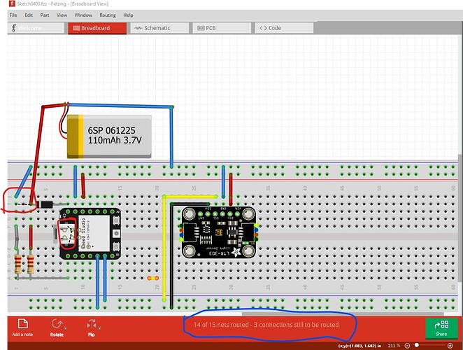
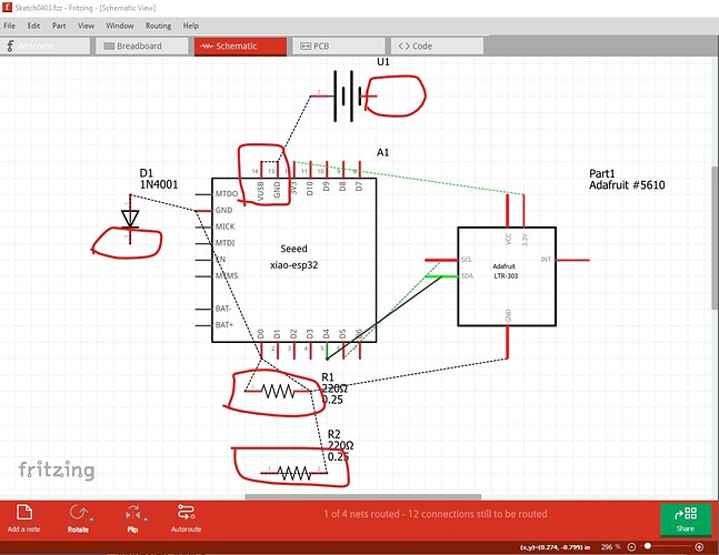
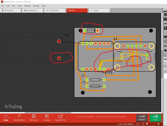
The 14 of 15 nets routed message (circled in blue) should say routing complete. The two rats nest lines circled in red show the nets that it is complaining aren’t routed. Schematic has a number of errors.
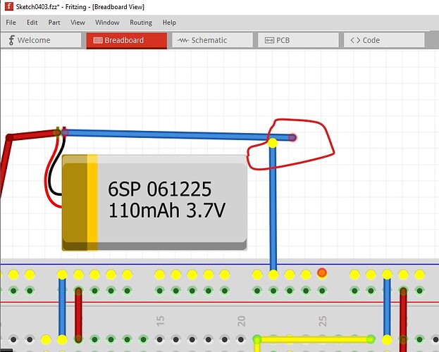
The battery isn’t connected to anything, nor is one end of the diode, both resistors are shorted. Pcb shows some indication of why the problems
The traces on the top layer are running through the SMD pads and thus will connect to them causing shorts. The traces are also overlapping which will also cause shorts. However removing them doesn’t make much difference.
Here is a trick that may help. If you click on a pin (here I clicked on the minus power strip) it lights yellow everything that is connected to that net. Here we see the blue wire to the battery negative terminal lights yellow but does not connect to the rest of the wire (and thus not to the battery.)
You can either move the LTR-303 off the breadboard and connect to its pins via wires or I could fix the part for you so it won’t short the breadboard. I think it is possible that you have also hit a Fritzing bug, and the safest course is to start a completely new sketch from scratch and try this again (leaving the LTR-303 off the breadboard until it gets fixed and connecting to it via wires.) Incidentally your diode is backwards as well, it needs to be the other way to block 5V from the usb from trying to charge the battery I expect (but I haven’t looked at their suggested circuit either!) As it stands the battery won’t run the circuit even if the battery negative terminal is connected which I expect isn’t what you want.
Peter
