Hello everyone!
I’m a new learner to Fritzing. Currently, I’m doing a wireless controller project, and I need this type of joystick. I’ve looked through all the sources but this part is no where to be found  Please let me know if someone has this type of joystick!
Thank you!

Welcome to the forum.
Electrically that joystick is just a pair of potentiometers, so electrically the existing sparkfun mini joystick part in the library will work. The connections are discrete wires, to there is nothing needed for pcb view. It will just be off board wires/connector where every you want to put it. The only thing a custom part is useful for, is making the breadboard view prettier. For just creating a circuit in Fritzing, I would probably just use a pair of pots.
Someone else may have, or decide to create, a part for this. There is enough dimension information on the page you linked to make that easy. The above information is to provide workarounds, so you can continue the project without waiting.
Thank you for your answer.
So in this schematic, the connections of the above joystick are just divided into another x2 GND and 5v power connections which basically the same when we wire them? Because I see in the regular joystick, they usually have 5 connections: GND, +5V, VRx, VRy, SW.
I have very little experience with electronics.
The 5 connection joysticks just tie the power and ground for the 2 potentiometers together internally, and provide a single connection externally. The SW is for any extra switch on the joystick. The one you referenced did not seem to have the switch. So if you wire the pots from that together, you would end up with 4 connections. 5V, GND, VRx, VRy. Just make sure you get the correct common 5V and GND. Otherwise the high and low will get reversed. Initially, just wire them up individually, until things work the way you and your code expect.
Thank you very much! Right now, I’m trying to rewrite this schematic again on Fritzing for my individual project at school. Can you please check for me if everything are connected correctly later on?
Post here, and someone will probably have a look at it. That image you posted is not what I would call a schematic. More of a wiring diagram, which is closer to the Fritzing breadboard view.
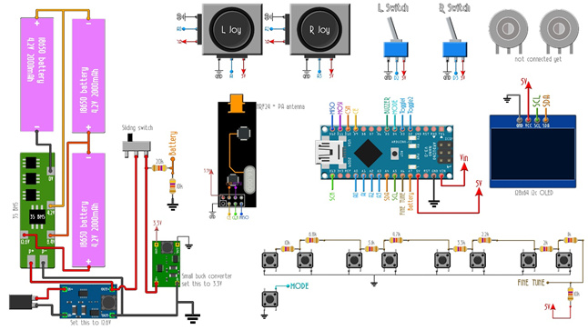
So these are the wiring diagrams that I have created following this tutorial: https://www.youtube.com/watch?v=YMF5NXeHOnk&t=657s


Right now, I’m having a trouble with transmitter diagram. At 11:30 he said that he connected a voltage divider between VIN pin, GND and connected to an analog input, but I just don’t see that in the diagram of his, only the beginning path from the VIN pin, but to where it connects? It would be great if you can explain further about that.
Just in case, this is my files:
receiver_coursework.fzz (17.3 KB) transmitter_coursework.fzz (128.9 KB)
This is his project (2 parts), so you can easily find out if I messed up somewhere in my diagrams.
Thank you!
The problems you asked about (VIN and voltage divider) are from miss-reading the original diagram, and a missing label on that diagram. The voltage divider has a label on it that says “Battery”. Circled in blue on this clip from the original. You connected that to the physical battery, but there is another “Battery” label on the Arduino A7 pin. That is where the voltage divider is supposed to connect to.
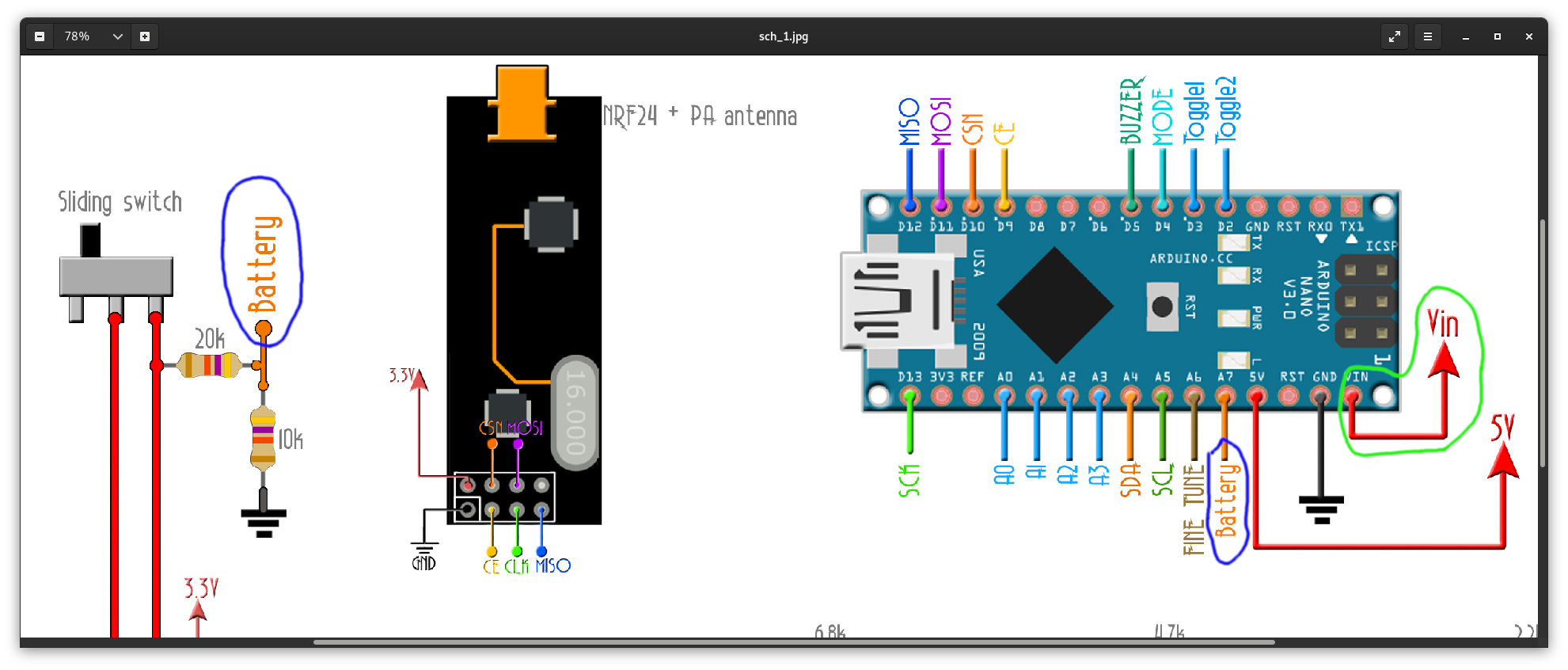
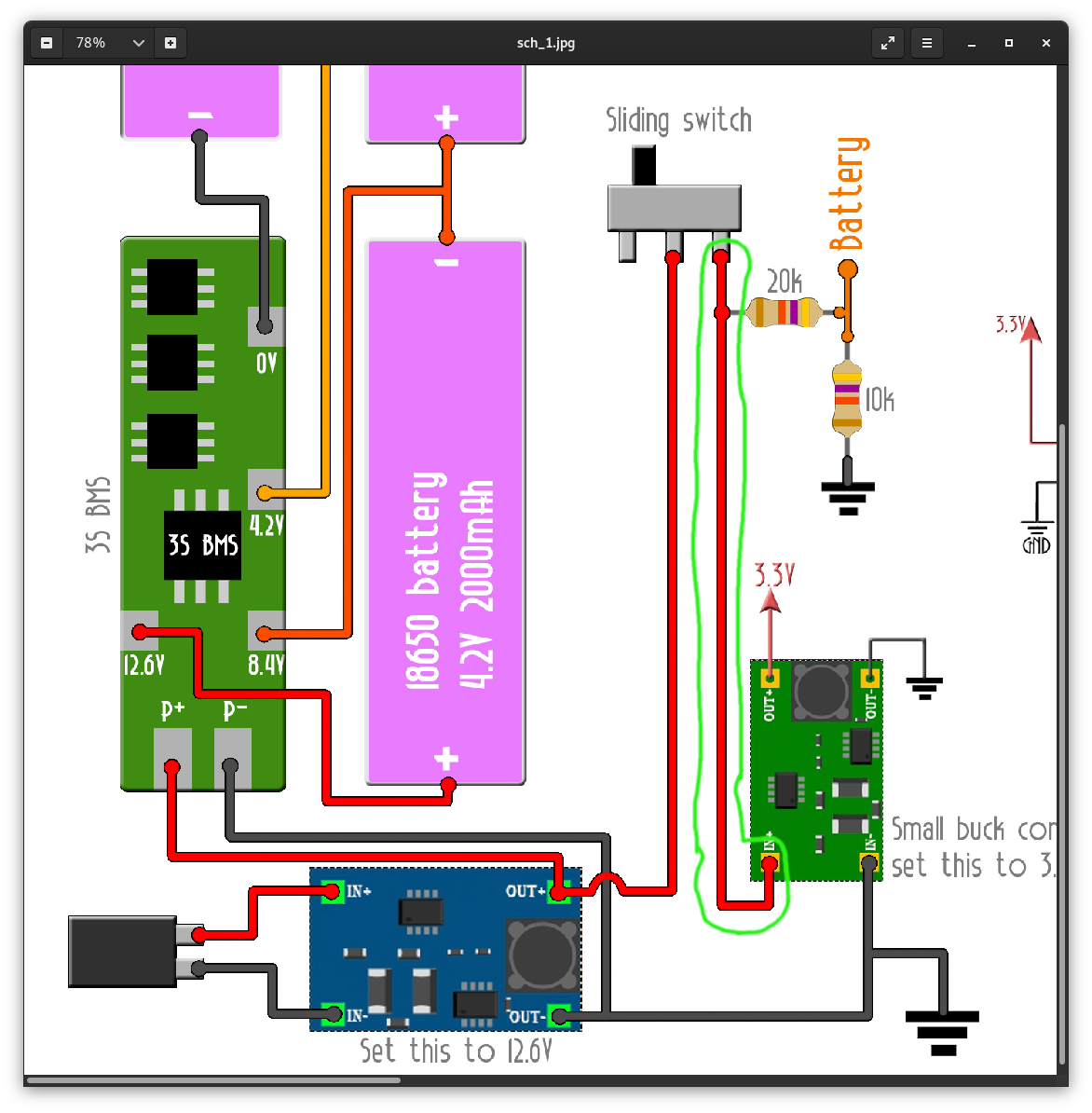
Vin, circled in green, is the voltage input to the Arduino. It needs to connect to the output (12 volts) from the power section, which is also connected to the end of the voltage divider, and input to the 3.3 volt converter.
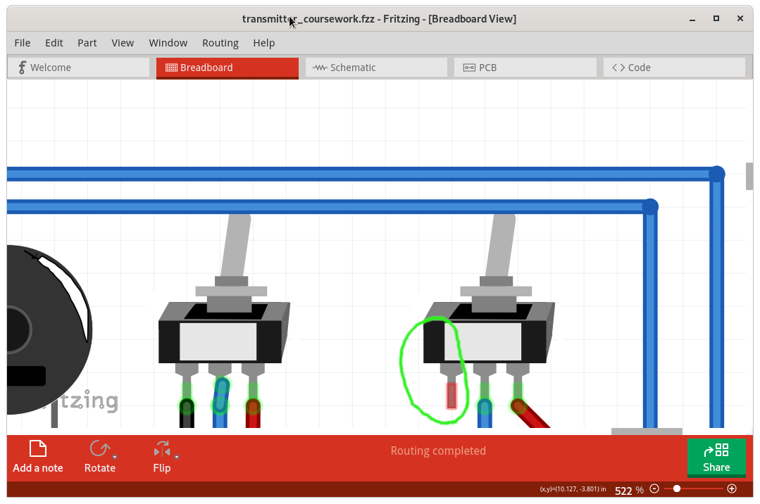
Looking at your transmitter Fritzing sketch, I see some problems. The ground connection on the right toggle switch is missing.
There are several other potential problems. These will not matter, if the only thing you are using the sketch for is to create a picture of the wiring. But if it will be used for more (I see “coursework” in the name), here are things to look at.
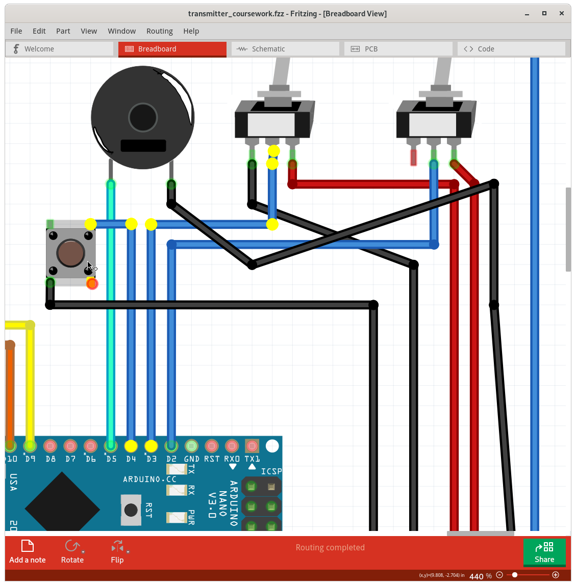
To start, drawing wires over top of each other does not connect them together. The actual connections are only at the ends of the wires. Fritzing makes it easy to tell which connectors are actually hooked together through the wires. Mouse down (and hold) on a connection pin, or a bend in a wire, will light up in yellow all of the connections (pins, wire ends, wire bends) that are connected together with the current wires. That also follows any internal wires defined for the connected parts. For example, the push button switches have 4 pins on them. Mouse down on one of the pins will highlight the connected pin, and anything connected to it through wires. So, this screenshot shows the the result with mouse down on the left end pin of the left toggle switch. Notice that ground on the right joystick ground pin shows yellow, but not the grounds for Arduino, left joystick, or NRF24L01 radio. Some the wires here do not look like your sketch. I moved them to try to see where the connection were really going for wires that were just on top of each other without being connected.

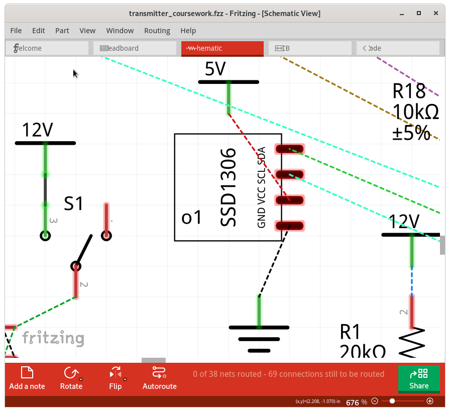
There are a several other parts that Fritzing does not believe are connected, that visually appear to be. Mostly for power and ground. One more I spotted, after moving the parts around on the schematic view, is that the end of the 5.1k resistor is not connected to the 4.7k resistor. The wire from the 4.7k resistor to switch S10 has a bend point in it, that visually lands on the 5.1k resistor, but it is not really a connection. Just a bend in the wire.
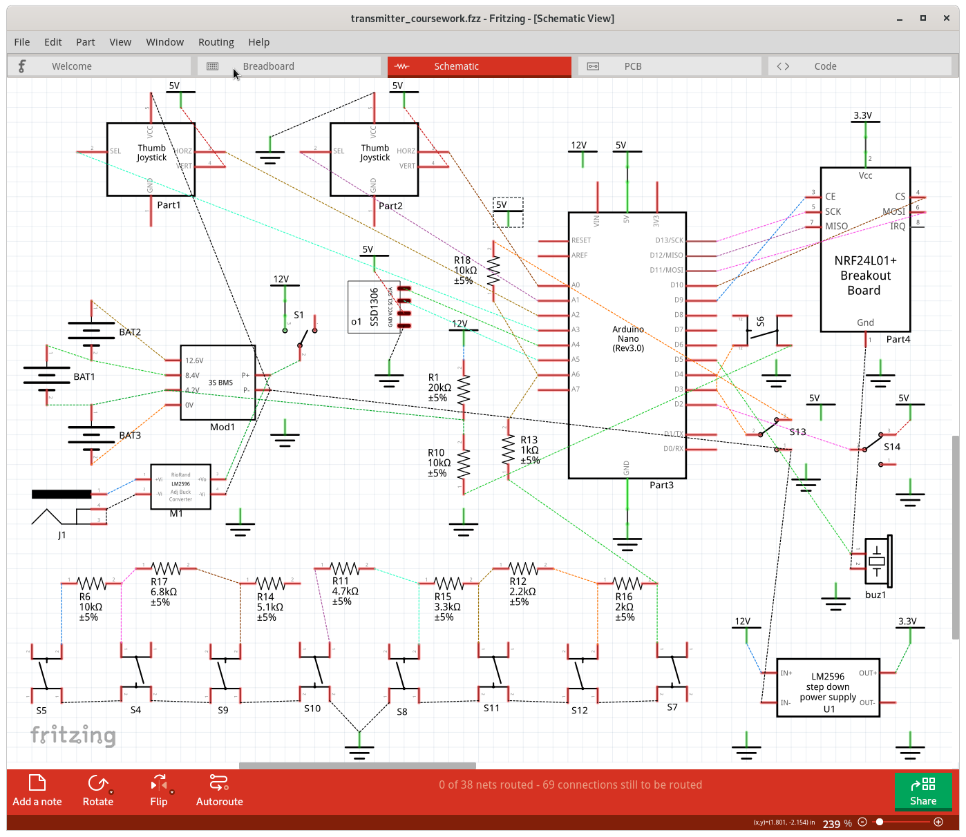
I laid out the parts on the schematic view somewhat in between the way they are on the original project wiring image, what worked fairly well with the way the current connections actually exist, and where the connections should go. The dashed lines on the schematic match to the wired connections on the breadboard view. I added standard power and ground symbols in an attempt to reduce the clutter. That was what initially showed that the grounds were not really hooked together. Anywhere there is a ground symbol that is not connected to anything, it is near a pin that should be part of the common ground set, but is not currently. Same for the 5V and 12V power symbols
The schematic shows Arduino pins D3 and D4 connected together. I can not see a reason for that with the breadboard wires, although mouse down shows them to be connected. I suspect you initially had a wiring error that you corrected, but got caught with one of the internal Fritzing wiring glitches, where it thinks a connection still exists after it has been removed.

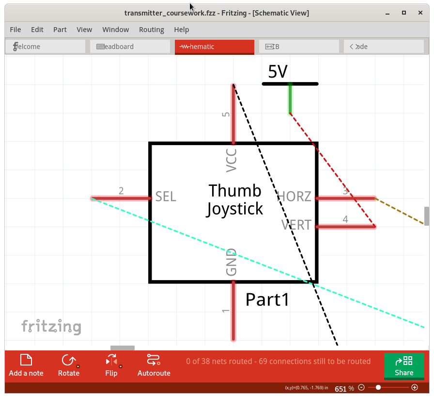
Where did you get the part files you used for the circuit? Since 7 of them are included in the sketch file, they would appear to have been loaded from custom files, and are not included in the Fritzing core parts library. The point being that (at least) the joystick part has errors in it. Checking the labels in the breadboard view, and where the wires are connecting to from them looks correct (other than the grounds not connecting together as described above). However, in the schematic view, the wires are not connecting to the pins with the same labels. The 5V wire shows connecting to “VERT” and the “VCC” pins are connecting to GND. I do not think any of the joystick pins in schematic view are connecting where the breadboard shows them to be. The part file was not created correctly.
The schematic view of the LCD screen seems to connect up correctly, but is not quite standard. The pins should line up with the 0.1 inch grid, and the connections to them should be at the ends of the pins instead of the middle.
I only glanced at the PCB view, to verify that the D3 to D4 problem was not because of a wire in that view.
Here is a copy of the sketch file after I played with it, and a screen shot of the schematic view. The only changes should be positions of the power and ground wires in breadboard view, without changing the defined electrical connections. Schematic view has been totally reorganized, with added power and ground symbols, but again without changing the electrical connections. Parts on the pcb view were moved, just to see if there was anything odd around pins D3 and D4.
transmitter_coursework.fzz (132.9 KB)
That should be plenty for now. I did not even open the receiver sketch.
First of all, I really appreciate your enthusiasm! You’re correct, I’m doing this for my coursework, although I only use the sketch for creating a picture of the wiring. But all the errors in the sketch that you pointed out also help me a lot in understanding how Fritzing works. And yes, half of the parts I downloaded from the internet because I just couldn’t find them in Fritzing, so incorrect parts are understandable.
Once a again, thank you for spending your valuable time with a beginner like me!