OK here are three parts that should do what you want.Normally use the first part
waveshare-rp2040-zero-tht.fzpz (12.7 KB)
it ignores the 10 pins on the solder pad on the bottom of the board which is probably normally what you want to do.
This one is a SMD part with all the pins present. I don’t know that it will solder to a board with the chips on the bottom, but if it will this should do it.
waveshare-rp2040-zero-smd.fzpz (13.5 KB)
and finally a THT part with the extra connectors.
waveshare-rp2040-zero-tht-extra-conns.fzpz (13.8 KB)
This one has the holes for a Harwin M50-3531042 1.27mm male header the cpu board would need a mating smd male or female soldered to it. That is likely to be too flimsy to survive long though. This will get you the extra pins in a THT implementation. The three of them look like this:
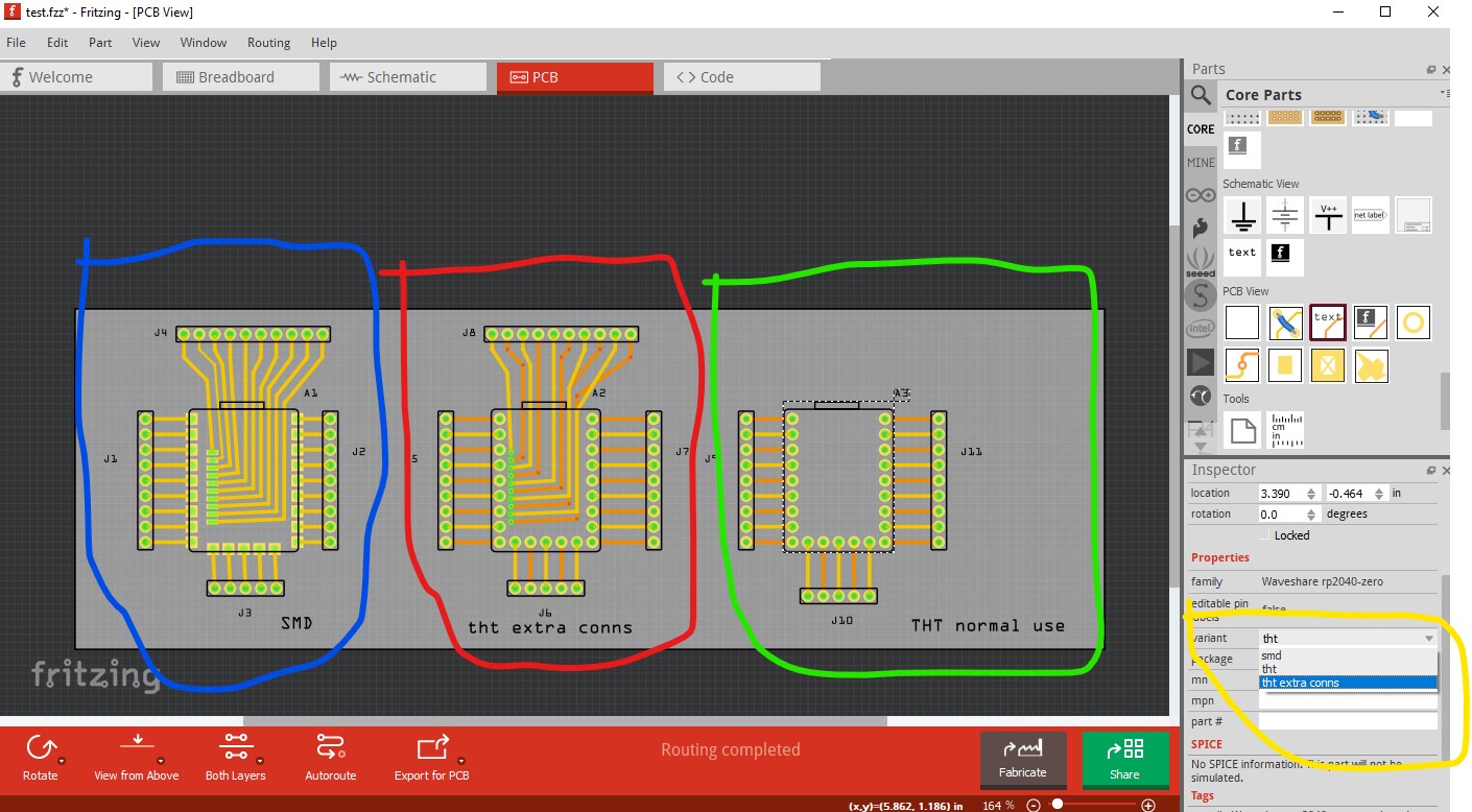
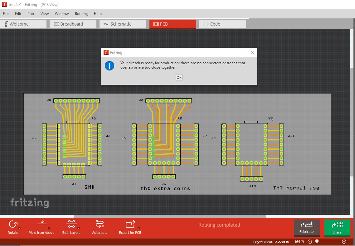
note the three types can be swapped in Inspector if the parts are saved in the mine parts bin (there is a bug that prevents this if the parts are not saved.) They pass professional DRC with the default rules.
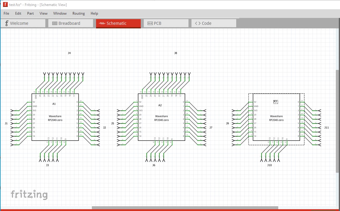
schematic
and breadboard (the bottom pins and the 1.27mm pins are set to female so they will not short on the breadboard but would in real life if there are pins present!) Note the THT version doesn’t show the 10 pins on the 1.27mm header.
eit: forgot breadboard!
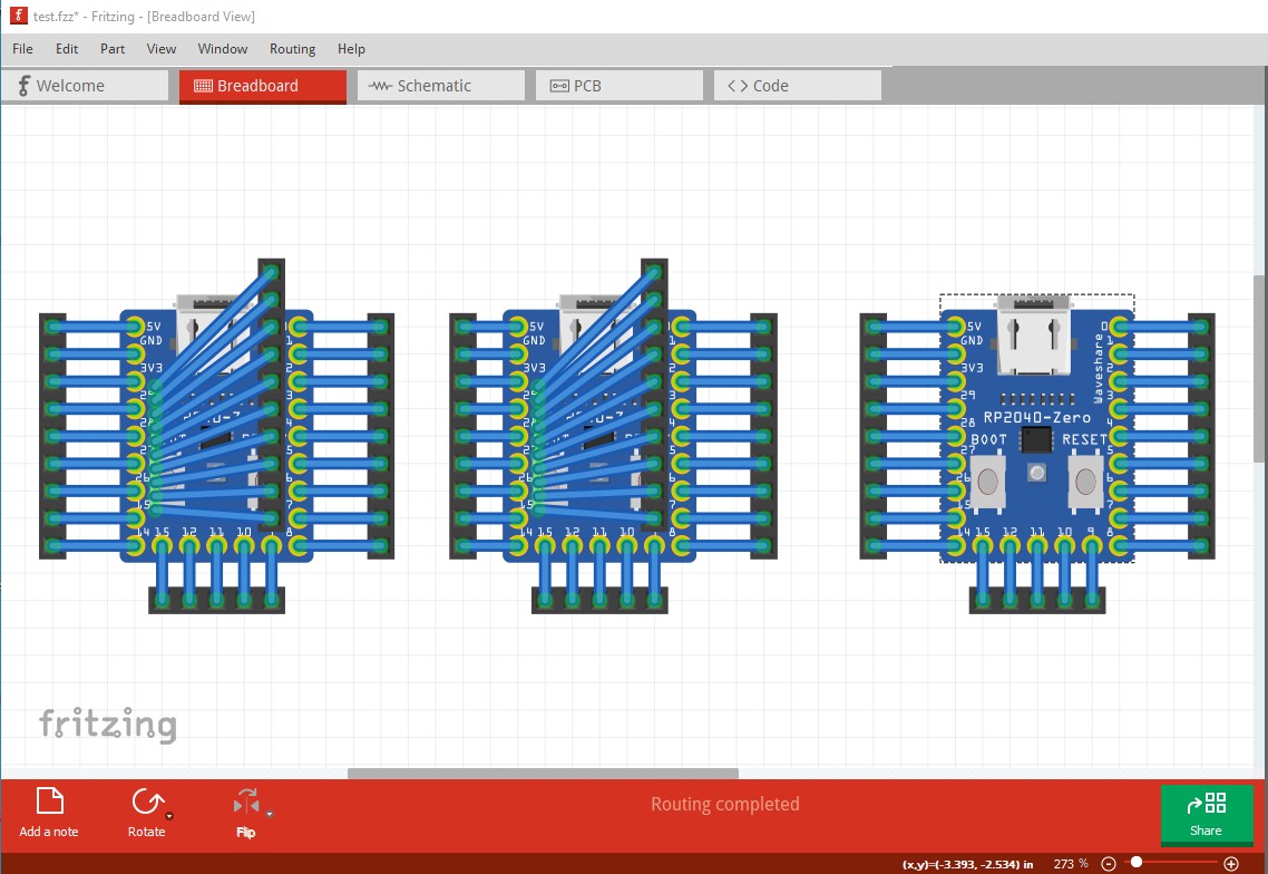
Note that it will probably be required that you start at the 1.27mm header pin to get a successful connection in breadboard!
Peter