I’ve been scouring the interwebs, bu havent found a part for this yet, and my part making skills are lacking. I would be extremely appreciative of any help. Thanks!
Name of the part
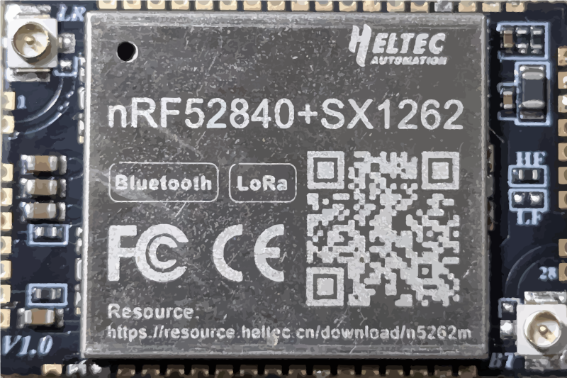
Heltec nRF52840 + SX1262 Mesh Node N5262M Module
However there is no footprint data and no indication of the offset for the pads which at 0.05in pitch is likely to cause issues. There documentation is very lacking (the referenced site above has multiple links that don’t resolve at least for me.)
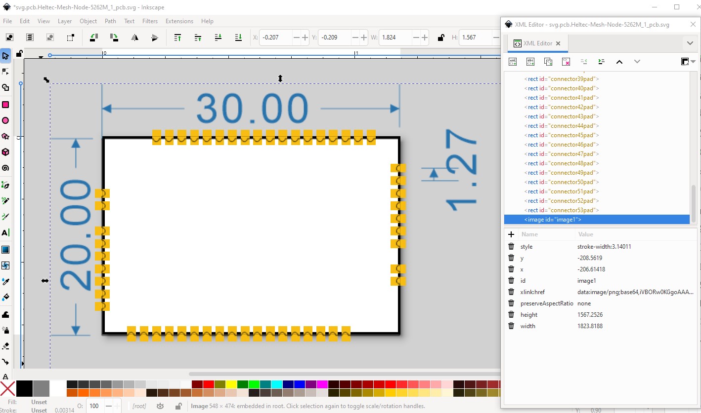
The exciting part is there is no horizontal or vertical positioning for the center of the pads. It is possible to try and position them from the above image (scaled appropriately) but at this fine a pitch it may not be successful. A proper datasheet would have a recommended pcb footprint with all dimensions, but that appears to be missing in this case.
Doesn’t look like it, there is a footprint file but no indication which CAD package it is for. I guess we will see how @RAPTOR7762 makes out. A footprint could be made from the image but it may not be accurate enough. You would need to be sure to print out the pcb footprint and compare it to a real part before ordering boards.
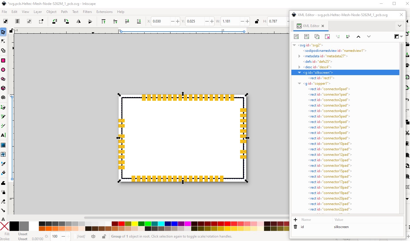
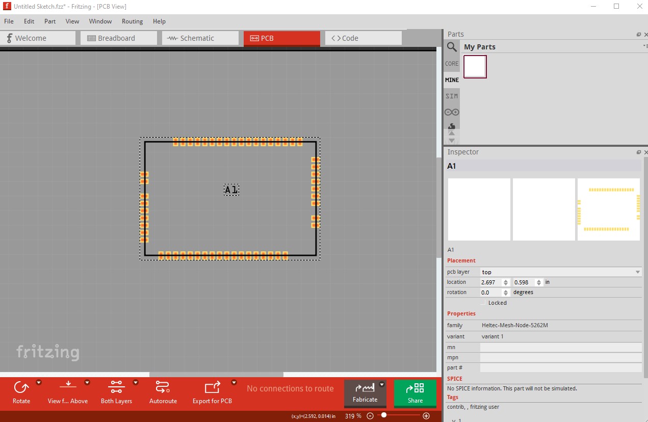
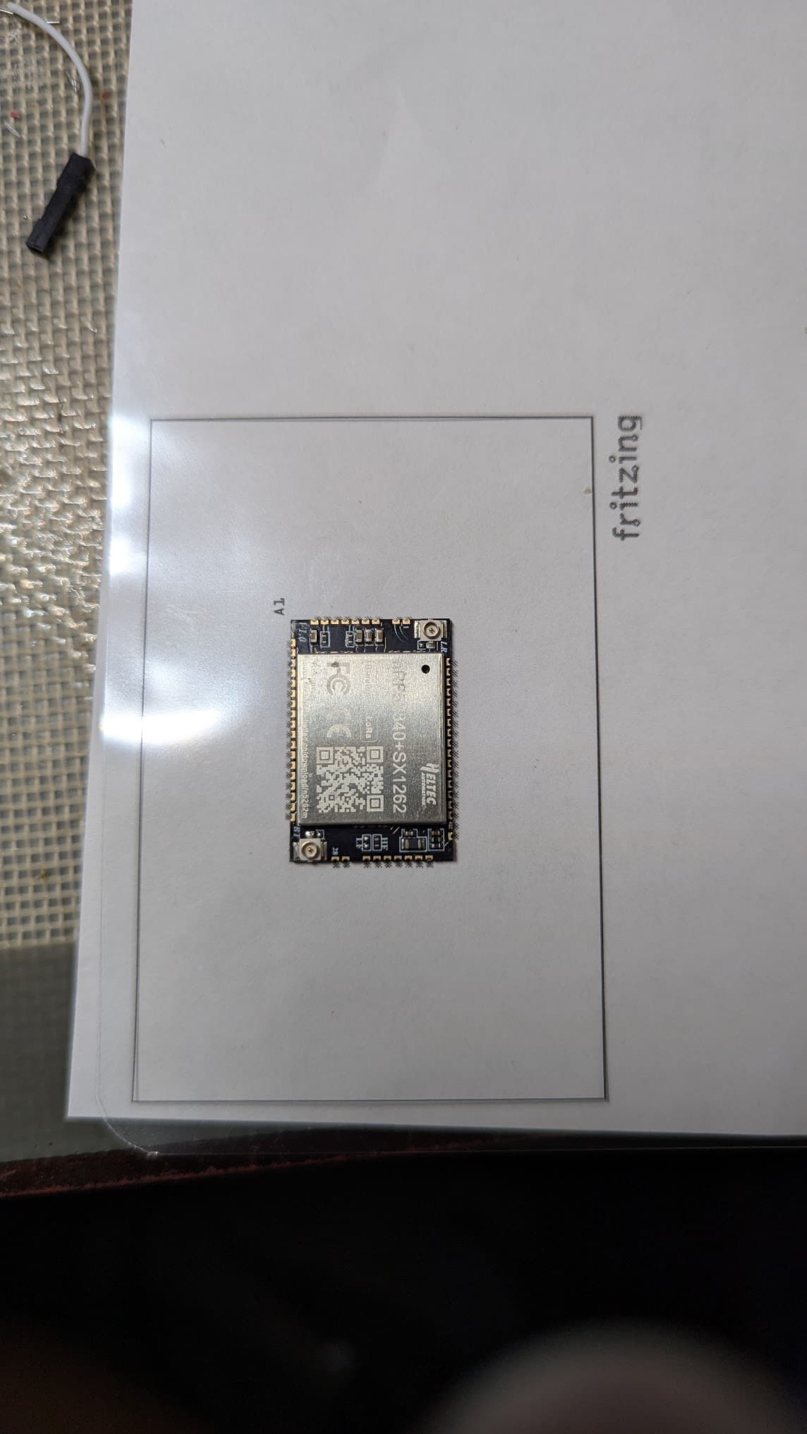
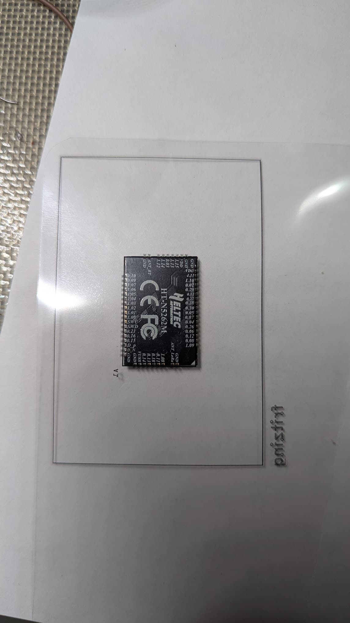
OK here is a pcb only part that should do the trick. If you can print this out (preferably on transparent overhead film) and compare it to a real part to make sure the pins align correctly (which I think they should, but checking is always safer!) The pads here are on exactly 0.05in (1.27mm) pitch with the png image scaled to exactly match the pins. The pad size is only a guess as they don’t give a recommendation but I expect it should do.
I just happen to have a pack of transparencies, and a laser printer. I’ll give it a size test. Do I need to do anything special to get the correct scale?
I have been using the pcb view to start planning out the board I am designing. I went through and labeled all of the pins in parts editor, would that be helpful with the part creation?