Hi there,
I have searched for the parts of multiple MKR boards but could not find them anywhere, Arduino has images of the board files but they do not have them as Fritzing files. The fallowing boards I would need.
Arduino MKR GSM
Arduino MKR Zero
Arduino MKR Vidor
I have no experience in making them myself, and so I was wondering if anyone would have the parts or be able to make them.
under documentation has an fzpz file although the other 2 do not. I found this because I came across an issue on github asking for help with another of these products where the fzpz file is corrupt (the pcb svg file is zero length). The rest of the fzpz file however is a mess and I don’t think it has ever worked.
Thank you, I will check the MKR GSM part soon, I have not seen it there.
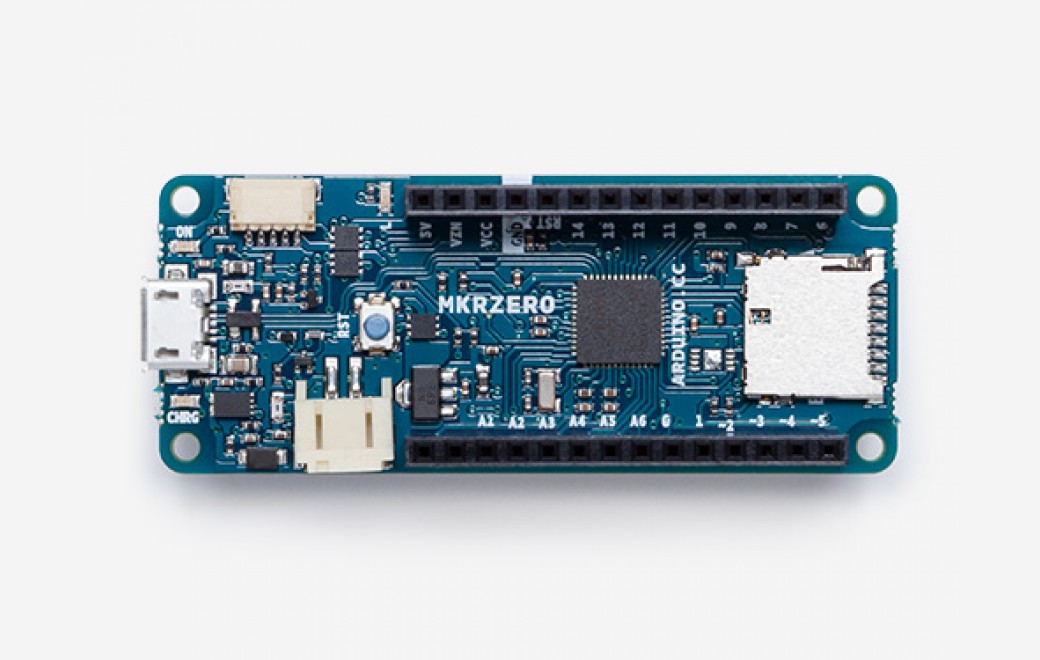
Regarding the MKR Zero, the only difference would be that it has an extra I2C port. The overall look of the board also differs. Here is an image of the board.
OK, I’ll modify the current Zero when I finish the Vidor board. It is being quite exciting in that there appears to be little documentation and a lot of pins and is thus going fairly slowly.
OK, finally the Arduino MKR Vidor 4000 part. It is a little large because I assumed you may want access to all the connectors. PCB only has pads for the two rows of .1 headers (all the rest are in connectors) but breadboard and schematic have all the connections. Some of them such as the JTAG port and the bottom row of the pcie connector are a little strange because they don’t normally appear on the top of the board but they are all there.
Sorry for bothering again. But I was wondering if you would have any spare time to make another board, It would be the Sony Spresense board. I did not find any schematics for that either.
Thank you,
Andrei.
This one was a dream, excellent documentation. As always check the pcb footprint before ordering boards, but I’m fairly confident it is correct.
edit: turns out I was over confident. The pin names in schematic are all wrong due to an svg editing error. I have deleted the incorrect part and will post a new one in a bit along with the extension board.
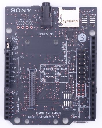
Thanks a lot, I know you done a lot and it is a bit rude of me to ask you for another component, but the Sony Spresense comes with an expansion board, image below. It would be quite essential for schematics with the Sony Spresense board. The Spresense main board clicks on to it.
Not a problem, this should be easy enough to do (and needs the first part in order to work anyway). I did wonder if you wanted both of them .
Edit:
OK, if you have downloaded the original Sony_Spresense.fzpz file please delete it and replace it with this one. The pins are mislabeled in the original one and (I hope, because I don’t have boards) corrected here.
And here is the extension board with the above daughter board installed. Note that you can (as you can in the real world) connect to the daughter board connectors. This isn’t however a good idea because there are level translators connected to the same pins from the extension board. http://forum.fritzing.org/
You are most welcome. These two are a little on the complex side for a first part, and part creation in general isn’t an easy task if you aren’t familiar with it. Once you are, creating parts isn’t all that difficult, but it took me more than a year to become familiar with it … I expect someone is going to come along and want the 100+ pin Hirose connector at some point to get access to all the CPU pins though and that will be a challenge.
 .
.