Hi,
just checking I have the correct fritzing part for a micro usb connector and is it positioned correcctly on the pcb. The pin dimensions seem correct but there are two addional holes - not sure what they are for?


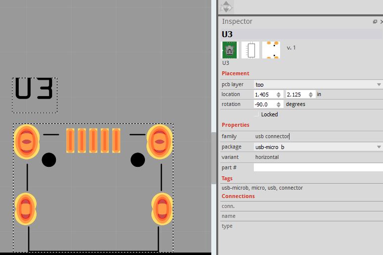
thanks, karl
Hi,
just checking I have the correct fritzing part for a micro usb connector and is it positioned correcctly on the pcb. The pin dimensions seem correct but there are two addional holes - not sure what they are for?
Presumably the part this was made from had pins that yours doesn’t although they aren’t holes but marks where you could drag a hole in the sketch on to the board if you needed them (and don’t appear to be working as they don’t appear on silkscreen here!)
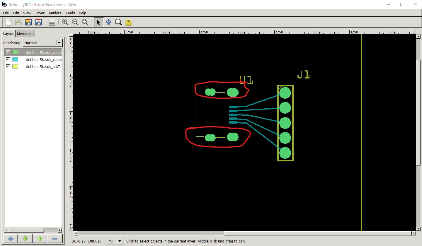
the thing of importance is to check the size of the drill holes (circled in red in the image which is the gerber output of the usb connector) that are being used to simulate the slots for the tabs (Fritzing and many board houses doesn’t do slots in general.) You need to check the size of the mounting pins and make sure they will fit in these holes (from the drill.txt file in the gerber output)
; NON-PLATED HOLES START AT T1
; THROUGH (PLATED) HOLES START AT T100
M48
INCH
T1C0.043889
T2C0.034306
T3C0.031500
T100C0.038000
%
T1
X024821Y013281
X024821Y016250
X024621Y013281
X024621Y016250
T2
X023103Y013222
X023340Y016273
X023340Y013222
X023103Y016273
T3
X024318Y013769
X024318Y015752
drill sizes are in inches so T1C0.043889 indicates a 0.43889in hole for the T1 holes. You need to make sure the tabs on your connector will fit in a hole of that size (or be prepared to file it out more, or modify the part if it won’t.) Printing out the footprint at 1:1 scale and checking it against a real part for positioning is also a good bet as the part is generic and may not match your particular connector.
Peter
thanks Peter,
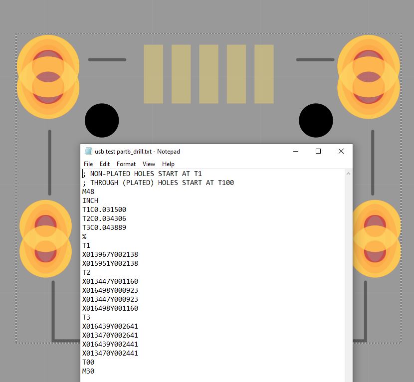
so I get the values in the drill text file as follows:
but it’s not clear to me which holes are which - I measured the connector so it has two different pin sizes: 2 at front: 0.0335 & 2 at back 0.0305. T2 & T3 resp? T3 the black holes? Aslo the pins are rectangular so it seems this is achieved by two holes sideby side?
I also zoomed in close on the pcb layout and compared the X/Y cordinates bottom right hands side and the pin distances match up pretty ok with the physicalpart.
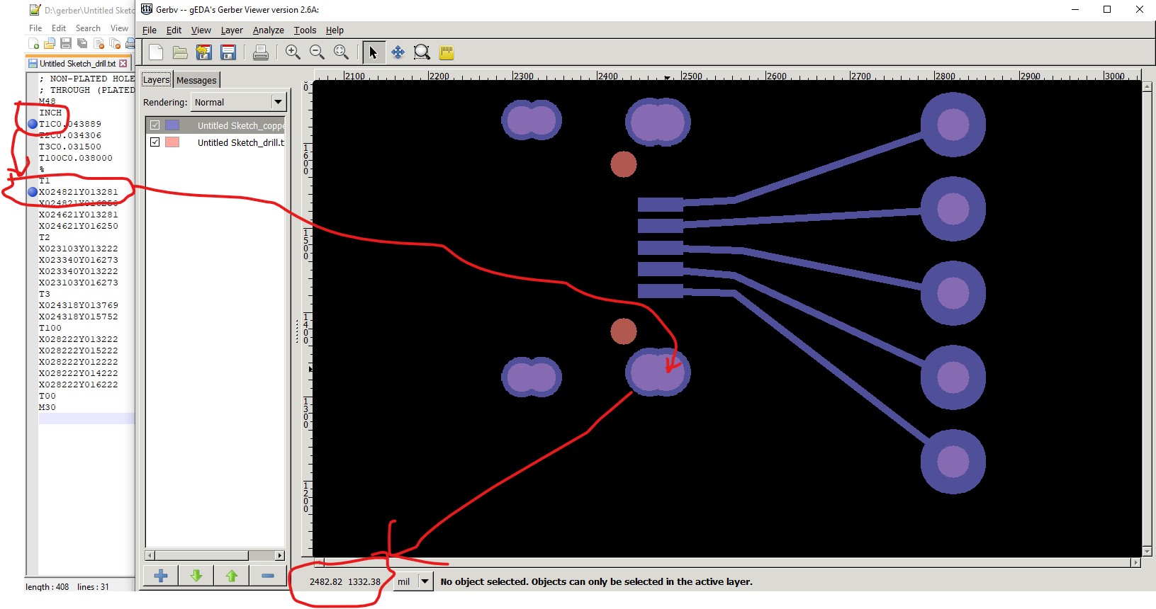
The T1 number indicates which set of drill X/Y coord will be that size, so you need to move to that coord in the gerber viewer (this is gerbv) to tell where the hole is:
here I chose the t1 holes then the first hole and moved the cursor in the drawing to the listed coordinates which tells me that it is the front hole of the bottom front pair (circled in red) that are 0.043889in and the two back holes are 0.03406in the orange pins (no copper around them which is why orange) are 0.0315, presumably you can ignore those as you don’t need them but they shouldn’t hurt anything as long as you don’t run a trace there.
Yes, Fritzing supports cutting slots poorly ![]() and most of the cheap board houses don’t do rectangular slots so typically overlapping holes are used to make slots. I haven’t tried this but folks that have say it works fine.
and most of the cheap board houses don’t do rectangular slots so typically overlapping holes are used to make slots. I haven’t tried this but folks that have say it works fine.
Peter
thanks for the info Peter, very useful indeed. I tried gerbv but found it difficult to figure out the lenght of the ‘rectangle’ from the two drill holes. however I was able to use the ruler tool in gerbv to give me this information and now I know the holes are plenty big and spaced correctly for my usb part.
BTW get this error when running the Design Rule Check even when I set the wire width to superfine.
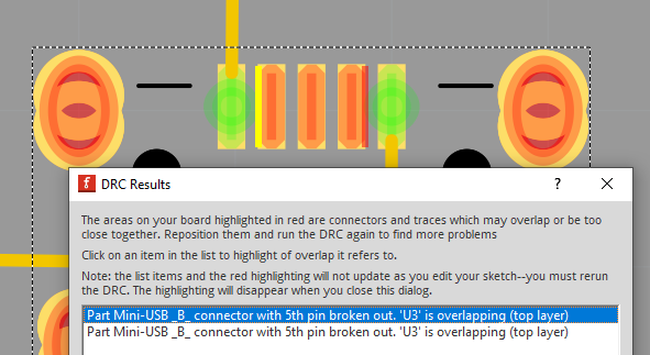
I presume this is ok?
-karl
Yes that should be fine I expect. There is either an error in the part that is causing the flag or the default DRC settings aren’t tight enough for the SMD part.
Edit: Although maybe not, I’m not seeing this on 0.9.6 even with 16mil traces
That said as long as the gerber shows enough clearance it should be fine.
Peter
yes, very strange, I tried to recreate what you’ve done but still same errors, also 0.9.6/win10
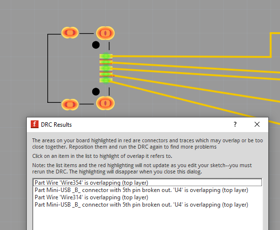
My fault, I had a custom DRC rule in from earlier. With it set to professional I get the DRC errors too.
Peter
I was trying it on ubuntu - same error.
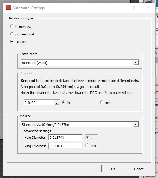
but when I changed to custom in the drc settings and set keepout to .007, the error goes away.
as an aside choosing ‘homebrew’ doesn’t work, it reverts to ‘custom’ - bug?
I’m not sure, it may be a feature in that you need to set custom rules if you are home etching. I expect the tolerances vary. Anyone how knew that the original intent is likely long gone though.
Peter