Part for breadboard with variable spacing

Hello,
Anyone got part for 830-point and 400-point breadboard with variable spacing?
I explain my problem: my dev board is too large to fit correctly into the breadboard, so I cut it into two parts and then inserted the dev board. See the picture below.

If no, how to modify the existing breadboard parts?

regards,
Michel

Does an 830 point match one of the available breadboards in Fritizing (I’d guess full or full+)?
A full/full+ is 64 rows wide (the difference being the red and blue stripes on the full+.) There are others available in the size pull down in Inspector.

This looks to be the picture and matches a half+ breadboard in Fritzing. Breadboards are a little tricky to modify, as the ones in core are dimensioned in px which causes scaling errors on modern Inkscape and parts editor can not deal with them so you need to edit the files. If you verify which two you want I can modify updated versions to split in half easily enough.

Peter

1 Like

Thank you very much vanepp.
Correct, the 830-point is the Fritzing full+ and the 400-point is the Fritzing half+
Possible to get parts for the full+ and the half+ split in half?

regards,
Michel

Yes, it is relatively easy once you get the svgs properly rescaled and dimensioned. I already have the full+ I will need to do the Half+.

Edit: While starting to split a full+ breadboard I discovered an error in my fixed breadboard. I (and possibly Fritzing as well, I don’t know.) I converted the group that is currently the pin definition to the first drawing element. But that isn’t correct. The circle (the third drawing element in the list) should in fact be the connector not the first element

currently my corrected svg uses this as the connector which is obviously wrong as we see here.

It should be using the circle two down as the connector, so first I need to correct FritizngCheckPart to do that and redo the Full+ breadboard part before starting the split.

Peter

Maybe another option could be to two breadboards…

ok I see. thank you for your efforts
waiting for your feedbacks. thx

While it is correct that you can use two breadboards to do the same thing, I still need to fix FritzingCheckPart.py to deal correctly with breadboards and fix the breadboard svgs. After that making a couple of parts for a split breadboard is fairly minor (split the breadboard svg and the .fzp file) and I don’t see a reason not to do it. It is just going to take me some time to fix up the development version of FritzingCheckPart to deal with the issues raised.

Peter

Thank you Peter.
I don’t know if it makes sense and if it is possible to take the opportunity to add additional “cutting” parameters to the breadboard inspector window? For example, cut the breadobard into parts, define inter-space between parts…
As illustration, see below of actual usage of breadboard parts when it is cut
image

What will happen is 2 parts full±top and full±bottom independent of each other. You can move them to where ever you like then lock them so they don’t move. Changing spacing in Inspector would need a code change, the capability isn’t there at present AFAIK.

edit: OK here are the full+ parts

breadboard-full-bottom.fzpz (31.8 KB)

breadboard-full-top.fzpz (31.1 KB)

and a usage example using a Lolin 1in (I think!) node mcu

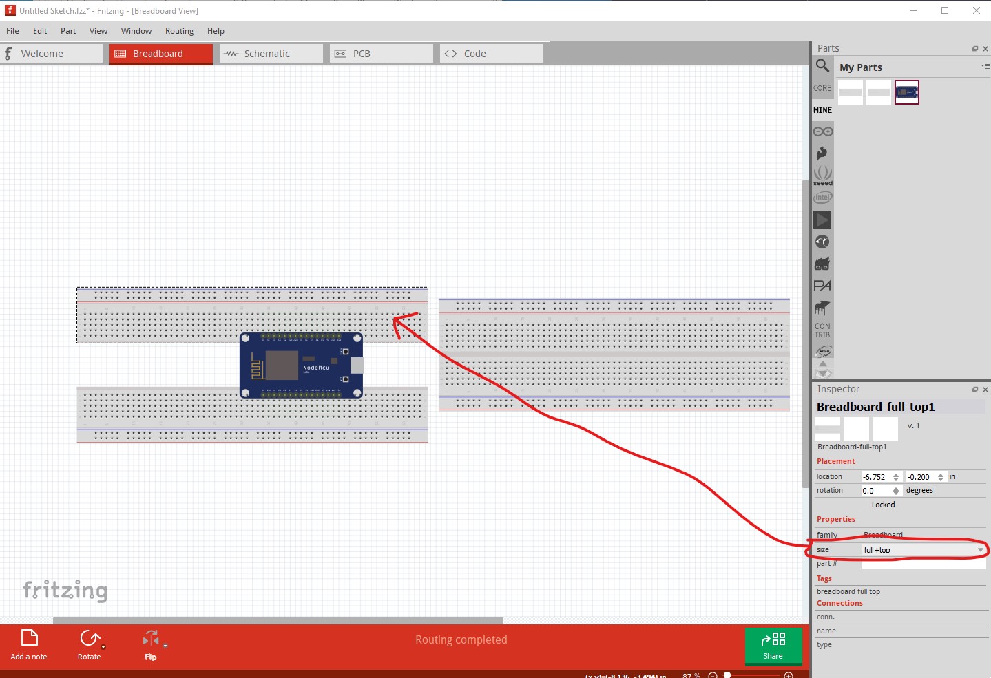
Now for the limitations. Loading the parts in to Fritzing doesn’t produce the full+top and full+bottom selections in the size field. Saving the parts in the mine parts bin then restrating Fritzing does put them there (I suspect this is a bug of some kind!) The selection pads on the two new parts are smaller by a fair bit than the original breadboard (which used the group of three drawing elements as the connector maybe.) That doesn’t seem to cause any immediate problem that I can see, but you are my test case, If you have problems with connections on my new parts that you don’t on the standard breadboard please post the part that is giving problems anr I will look at it. At worst I may need to make a new bigger and invisible connector circle if problems show up (I really dislike connectors defined as groups, if you ungroup the svg you lose all the connectors definitions!). I’ll move on to doing the half+ next.

edit2: and the two half+ parts

breadboard-half -bottom.fzpz (18.3 KB)

breadboard-half -top.fzpz (18.3 KB)

Peter

Hello Peter,
Thank you very much for the parts. It works great!
One remark: I have anchored the dev board to the two half breadboards as you did on your picture. But when I move, or rotate, the dev board, only one of the half breadboard moves or rotates. The second one stay at its place. Any solution to make them move together?

thank you
Michel

The only one I can think of is select all three parts before doing the rotate. The two halves of the breadboard are separate parts and rotate independently. The other thing you could do is make a single part out of the two breadboards, but then you can’t change the spacing between them without making a new part. So you either get a variable amount of space between them or both rotating but a fixed offset not both.

Peter