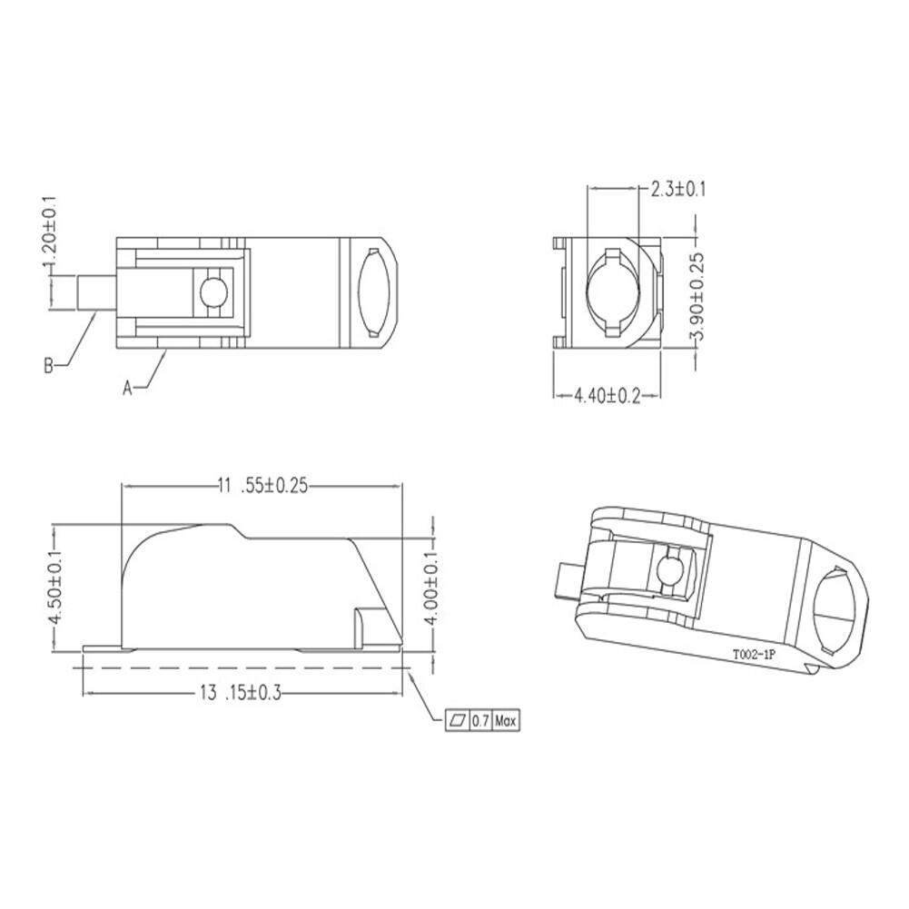
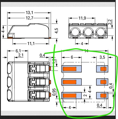
It is fairly easy to make these, but I have one question: why are there two pads?
I assume (perhaps incorrectly!) that the two pads circled in green connect to each other as the idea appears to be to connect a wire to the connector, but is that correct or or is something else going on? I can’t find anything like a schematic or connection diagram for these things. It may well be the pads connect together and are only separate pads for mechanical strength (that would actually make the most sense!) If you already have one verifying the two pads connect to each other would be useful.
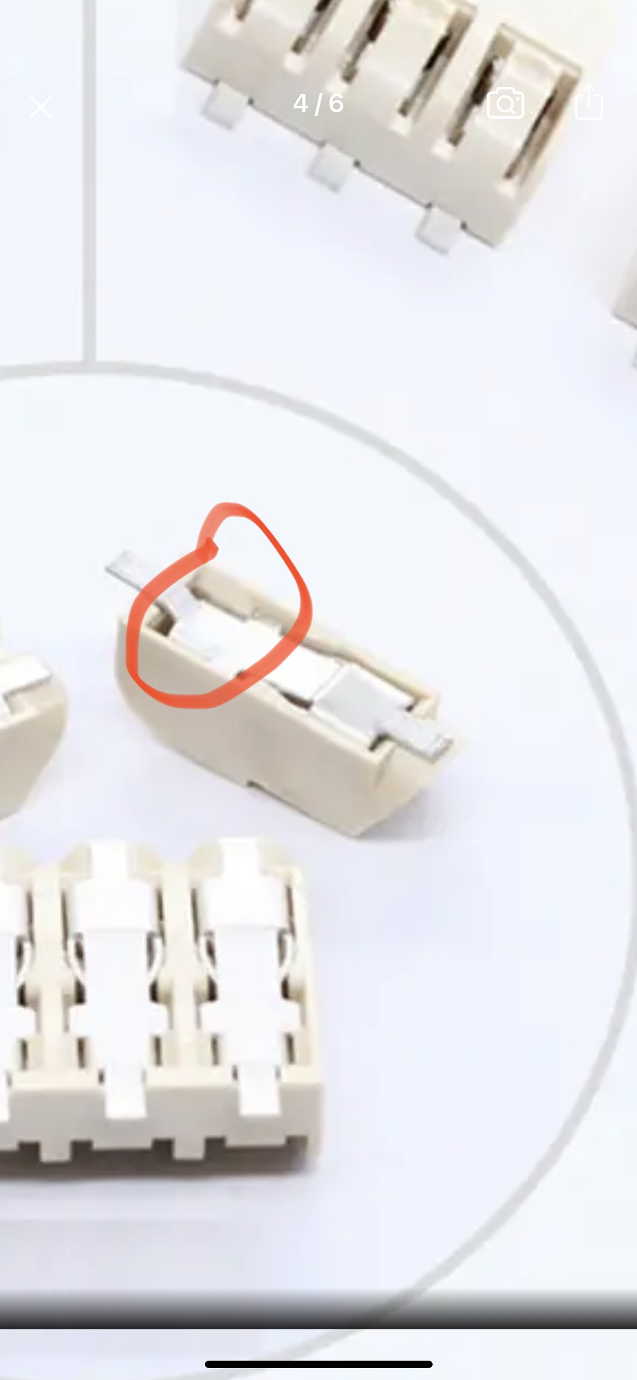
The connections ARE indeed connected. I think that blueprint is a little deceiving, I think the “disconnect” is actually just to show a small dip in the metal strip on the bottom - I’ve circled red here.
In the blueprint, I’m pretty sure those pads shown are only the surface touching parts of the strip if that makes sense - the gap is where the strip dips upwards towards the switch. The contact itself though is joined and conductive. I did just double check with my multi-meter as a sanity check and confirmed it is connected.
It’s possible that cut out area could be flexible since it houses a kind of spring - after all, it’s a “quick release” style terminal.
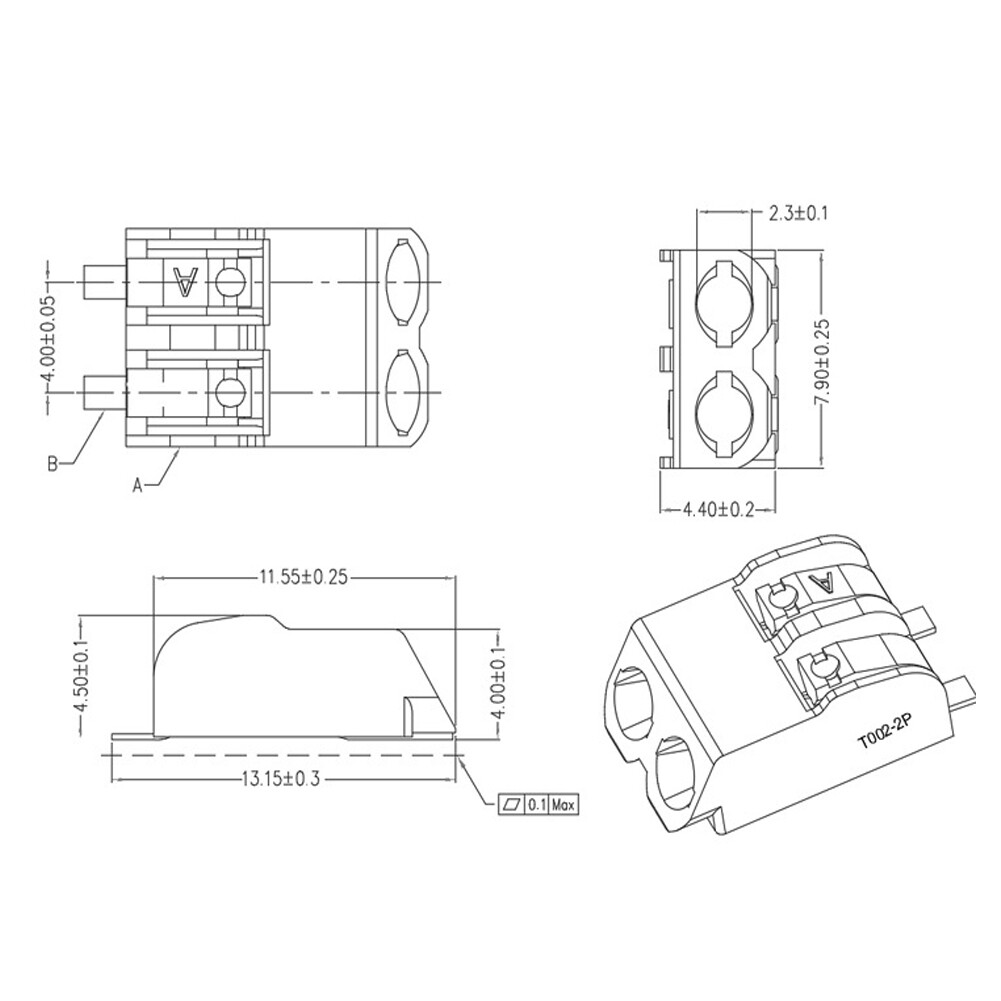
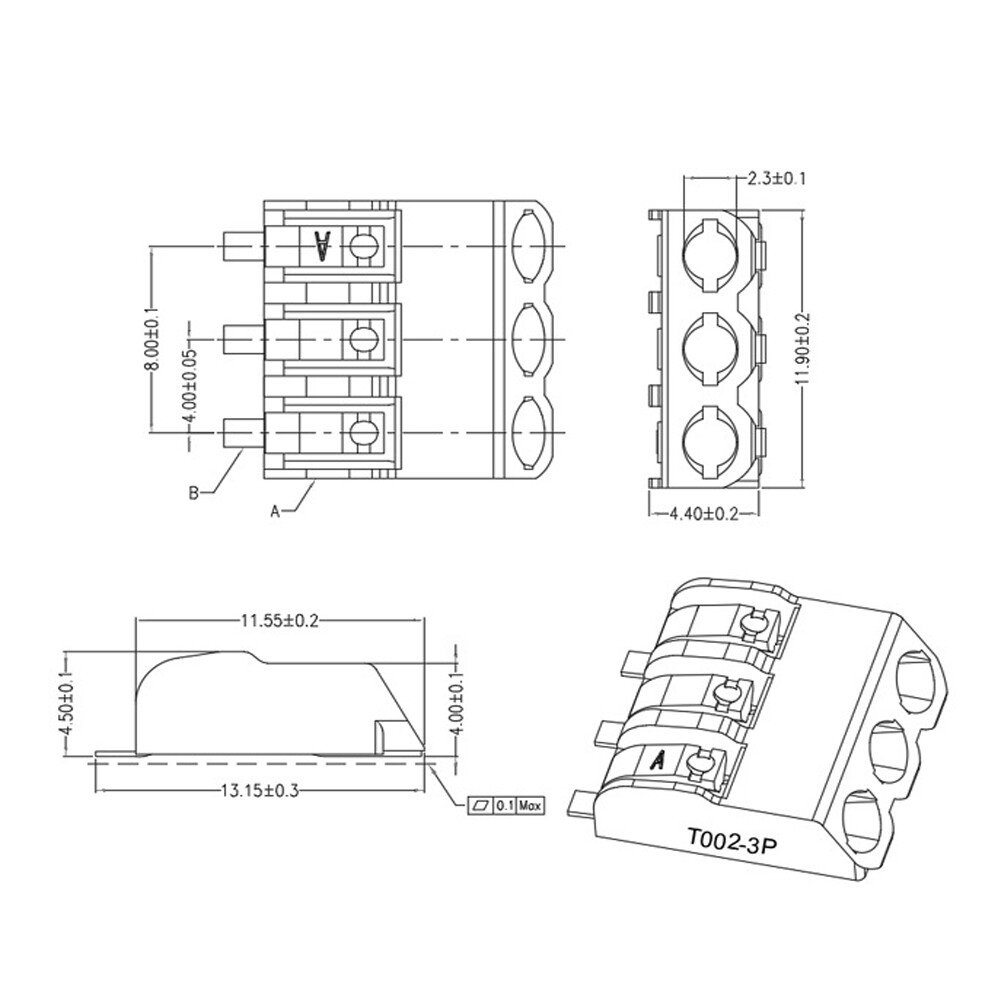
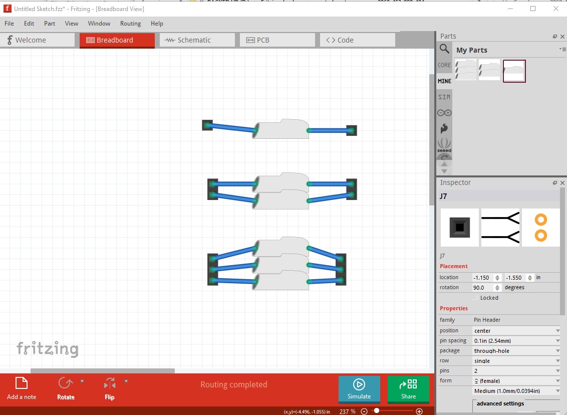
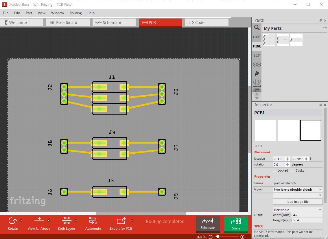
Yes I saw that picture after posting and figured I was correct in my assumption, but a physical check is always better . In any case here are the three parts:
Breadboard isn’t perfect because I just duplicated the one pin version for the other 2 and didn’t meld the outlines together, but it serves. Due to the 2 pads in pcb there are two connections for each pin so you can connect the wire to the input pin on the front and it will connect to the actual circuit connection on the back.
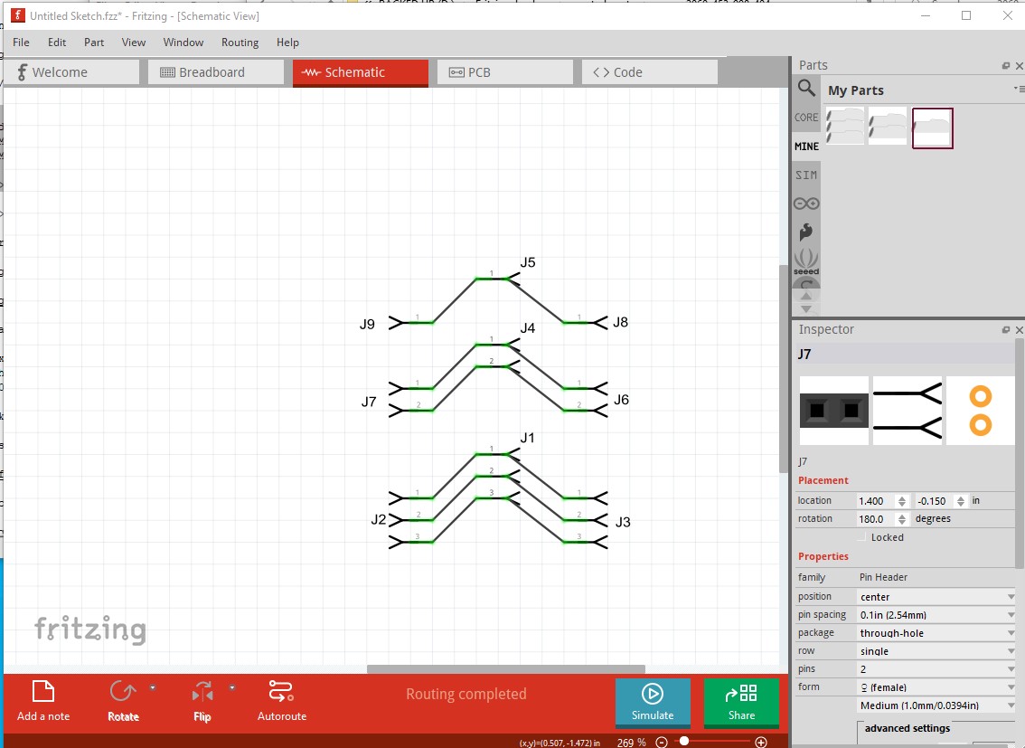
but the two pins are bused together so they are common. I chose to move the terminal to the back of the connector in schematic to reflect where it physically connects (the angles above are to make sure the terminal placement is correct, in practice you would connect the wire straight in I expect.)