Please help in creation of fritzing library part of a single or series for the Arduino OPTA PLC RS485 Model# AFX00001. This is a micro PLC controller built on a similar shared MBED architecture as other Arduino boards, but with very different circuit design, comms, plus built in relays. They share common similarities with the Portenta series as well. Comms between Units is done thru a UART I2C interface between them. This is built into the “AUX” port on the sides to daisy-chain.
There are 3 models of “Master” PLC’s:
- AFX00001-OPTA RS485; on-board Ethernet and USB-C ports, plus RS-485 connectivity
- AFX00002-OPTA Wi-Fi; on-board Ethernet and USB-C ports, plus RS-485 and Wi-Fi/Bluetooth
- AFX00003-OPTA Lite; on-board Ethernet and USB-C ports
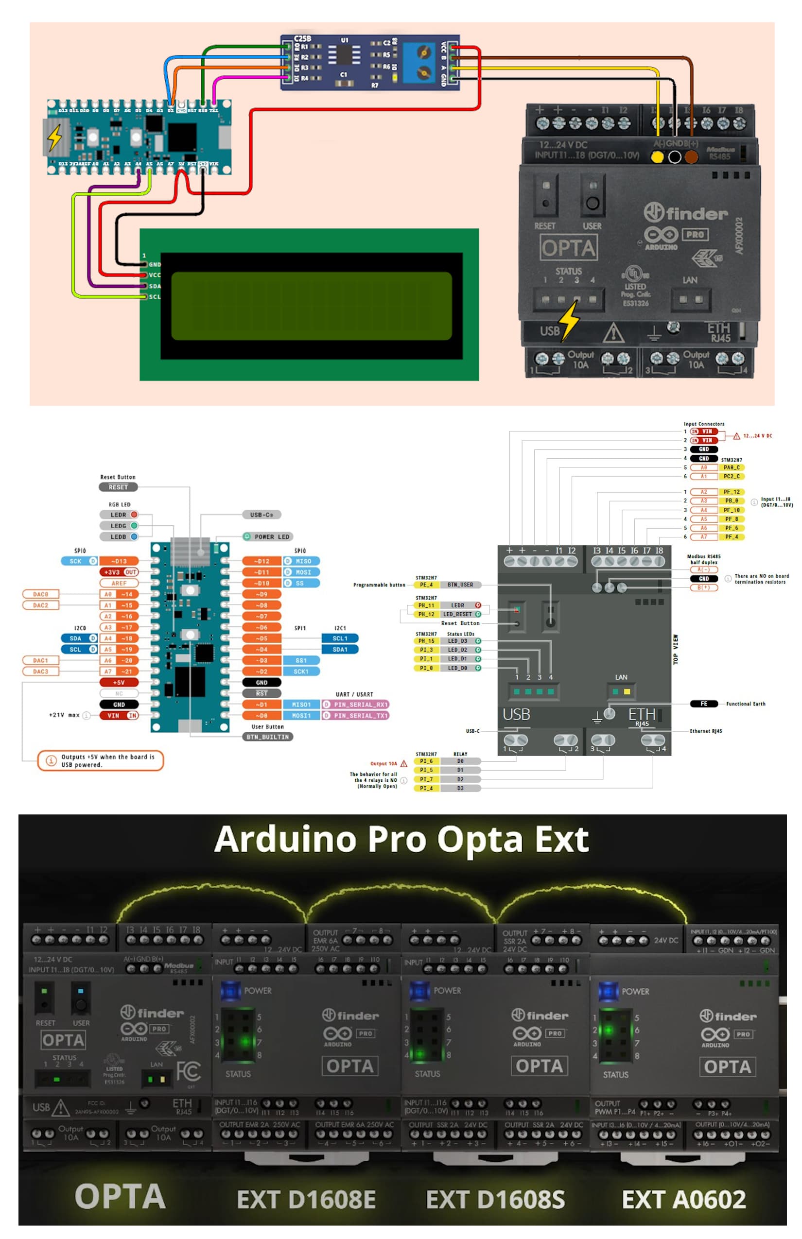
There are also “Slave” expansion modules for increased I/O’s:
- AFX00005 - Opta Ext D1608E (with electromechanical relays)
- AFX00006 - Opta Ext D1608S (with solid state relays)
- AFX00007 - Opta Ext A0602 (Analog Expansion)
I am trying to interface the PLC with a 16x2 LCD I2C thru MODbus comm to a MAX485 and then a Nano Matter (#MGM240SD22VNA) as a receiver/processor for the message. Not only was figuring the circuit tricky, but I’ve had very little luck in the ladder logic and programing this. I was attempting to get my feet wet with an example of:
- When user button is pressed on the OPTA, then the LCD displays “Hello World to the OPTA!” thru the ModBus RS485 on the PLC, to the MAX485 signal processor, to the Nano Matter, then finally to the LCD.
Any help on this would be greatly appreciated!
Datasheet
The official documentation of the part manufacture is linked here: