CP2102 USB UART.fzpz (18.7 KB) 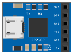
My first attempt to create a part. So, be kind with me 
I ran that part through FritzingCheckPart. Here is a summary of what it reported.
There are ‘px’ units on font-size attributes in the breadboard and schematic view svg files that Fritzing is known to not handle well. The text size can change from what was intended. Fritzing wants just numbers, without units.
Silkscreen content should be all one colour. Previously that was white. The new convention is to use black graphics for pcb silkscreen. Fritzing automatically converts (and so does the FritzingPartsCheck tool), but for future reference, black is preferred.
No terminalIds are defined for the schematic view of connectors. Those are needed to get the wires to connect to the end of the pins, instead of the middle.
Connectors should start at zero (connector0) and increase from there.
Inspected the part files, and testing out in Friting also finds.
The graphics for the breadboard and icon are visually the same. It is not necessary to have a separate file. The icon view definition can just point to the breadboard image file.
“USB UART” is not really a part number. If no specific part number exists, leave is blank. The user can fill it in for the part they actually use.
The label is intended to be a short prefix to use, to differentiate (by appending a sequential number) from other parts in the sketch. “FTDI USB UART” is rather long for that. “FTDI” might do. Typical (simple component) labels are down to single letters. R, C, Q, U for resistors, capacitors, transistors, IC chips.
The schematic connector pins have been drawn as dots (very short lines). They should be 0.1 (or 0.2) inch long lines, to have a decent target to connect to when drawing wires. The dots are hard to click on to start a wire. The associated terminalId (mentioned as missing by FritzingCheckPart) is what determines where the wire will actually connect to graphically after initially drawing. Without a terminal, and with a longer line, the wire would connect to the middle of the line.
@microMerlin Thank you very much for your time and effort to analize this part and also the other one I’ve uploaded. I really do appreciate it and will dig into each and every issue. FritzingCheckPart seems a good tool so I will install this too. Seems I have some work to do 
Thanks again!
I tend to use Mod (for module) for modules like this.
Peter