I’ve made quite a few parts and generally don’t bother worrying about this kind of “stuff that isn’t perfect” when they’re for my own use. But…
… it is annoying to have an unsolved mystery like this:
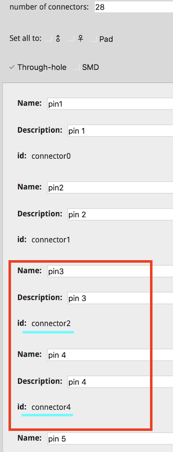
Connectors seem to always start at “connector0” but, adding connectors skips a number.
For example (screenshot) shows: connector2 then the next one is connector4. Question1: What happened to “connector3” ?
I’ve repeated this starting with only 1 connector (connector0, Name = pin1) and when changing the number of connectors from 1 to 5, for example, connector1 gets skipped and continues from connector0 with the next one being connector2, not connector1. Question2: How to correct this and get sequential connector numbering ?
Question3: How to start connectors at connector1 (not 0) ?
This would appear to be a parts editor bug. Parts editor wasn’t finished when development ceased so it has both bugs and parts that are incomplete (that is part of why I don’t use it). It doesn’t support a number of elements: bendable legs for one, split copper0 and copper1, and probably others I don’t know or remember at the moment. Hopefully with development restarted this will improve. That said, I don’t remember hearing of this particular fault before.
I expect the only way is to edit the fzp file with either an editor or a script that will change all the sequence of connectors back to what they should be (on a large part that is a lot of work unless scripted!) I tend to delete the connectors entirely and replace them with boiler plate generated by this python script.
I then have to edit the fzp to add back in the pin name and description fields. Not the desired workflow, but less work than trying to fix parts editor at the moment. I think a complete rewrite of parts editor in javascript is still proceeding although I haven’t heard anything of it lately.
You can do that in the fzp file and nothing I know of but the parts check script objects. The part file format does however specify that connectors should start at zero and be sequentiaI, so something may break if that isn’t true (but I don’t know of anything, many of the eagle2fritzing parts start on non zero pins, and are not sequential and appear to work fine. I think the reason here (but no one that would have known was still around when I joined Fritzing) is C++ array addressing (which starts at 0) against common pin numbering (which starts at 1.) For internal storage, pins starts at 0. (so you don’t waste the first array slot in every part.) For external display it starts at what ever pin number you set. If the pins are not sequential (possibly only in parts with subparts because that is the only place I’ve seen it happen), the “hover on the pin and get the description” function screws up. For pin sequence (internal) 0, 1, 3, 4, 0 and 1 display correctly, 3 gives random garbage and if I recall correctly 4 gives the data for 5 (it has been a couple of years since I discovered this) and it recovers on 5. I think I tried to reproduce it on non subpart part and failed so it may need subparts to fail.
I figured out a similar answer… after using a different starting part to work with. Generally I use the Antenna part - it’s clean and works well.
I used the Mystery part for today’s part starting point and that was the problem.
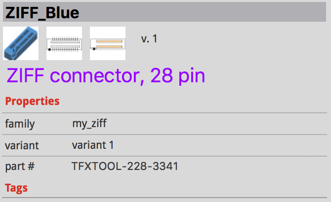
Anyway, after editing/tweaking the .fzp, I have what I want… Screenshot of it in the Inspector.
(FYI - though not a part of this Part, I’m now able to include tables, boxes…etc in the .fzp (you’ve seen some parts with tables etc, CSS is the trick to use in .fzp). And, I was able to use a real photo (or .png) for the Icon (after tweak in Gravit).