It appears (as I remembered) that Fritzing will in fact render gradients if you can get them in. It appears parts editor doesn’t support them, but doing them manually (not using parts editor) appears to work (although I don’t necessarily know what gradients are supposed to do). This is your svg above, cleaned up a bit (may not be necessary) and inserted in a part where the gradient appears to be rendering fine:
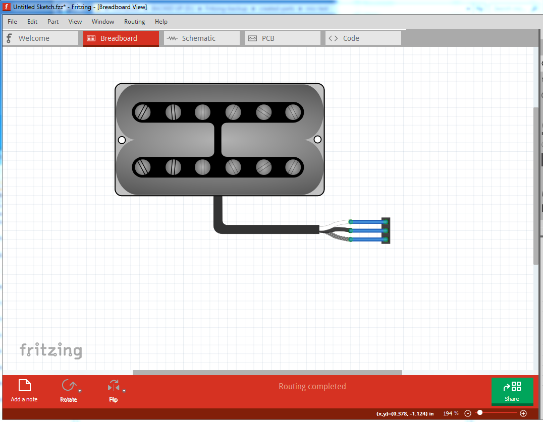
and the part that creates the above bb image:
mic-test.fzpz (10.5 KB)
If you download the fzpz file and unzip it you will get an ungrouped and regrouped copy of your original svg (with only a single breadboard group) and the three connector pins defined (they were not defined in the original svg. and since I am not using parts editor to set them, they must be defined in the svg itself) Schematic and pcb are from an fc-51 part because it happens to have 3 pins (and are thus wrong for this part, but keep Fritzing happy with the pin definitions in schematic and pcb). The fzp file was modified to refer to the current file names, but the pin descriptions will be wrong. As far as I can see Fritzing is rendering the gradients, but you should look it over and try others to make sure that is true, because as noted I don’t know what the gradients are supposed to do, but it looks the same as what Inkscape renders for the original svg. You can find instructions on creating parts without the parts editor in this tutorial series:
My network connection is still down, so it may take some time for me to reply to questions (I’m posting this from a borrowed machine.) As well the parts checking script (although it didn’t in this case) will sometimes complain (incorrectly) about no layerId because if has found drawing elements in the definitions section of the svg. That is on the list of fixes for the next version.
Peter