Part breadboard with gradient

Hi, I wanted to know if it is possible to create a part with a gradient… I made a part in inkscape and applied gradient to make it look prettier, but when adding it to fritzing that layer does not look … it appears blank or empty.

It is a detail, I can make the part in only one color, but I want to know if it can.

Thanks

1 Like

I don’t know - vector drawing is all XML code so maybe coding each pixel might be too much -, but maybe opera_night might because he knows a lot about drawing.

If you want to upload the part fzpz with the 7th button above I can take a look at it, ie, it might be a format problem.

Fritzing supports “SVG Tiny”, plus some extras. I am not clear on the extras, but I found this reference which starts out with

According to Adobe Illustrator Help – Saving artwork: Save in SVG format, SVG Tiny does not support gradients, transparency, clipping, masks, symbols, patterns, underline text, strike through text, vertical text, or SVG filter effects.

I have seen transparency (opacity) in svg files used for Fritzing parts, but have never checked closely to see what actually happens on screen. Memory says that the opacity settings did get through to a fritzing exported svg image though. So you could try specifying a gradient, using the part, exporting the view to svg, then finally viewing the image using a program that DOES support gradients. Depending on your needs, that might be usable, if that export can be the view that people actually see.

Hello, first I wanted to thank you for the answers … I tried many times to add the svg but I never had a good result from the fritzing editor, the images are not seen … today, I don’t know why, fritzing recognized the gradient .
But when saving the part, the graphics again look bad.
I send the fzpz file for you to see and also screenshot.

I am making many parts of microphones and connections mainly for guitar and bass, as soon as I finish adding all the parts I will upload it to the forum to share … there are like 100 types and connections of mic jajjaa gave me a lot of work

Gretsch Filtertron.fzpz (19.0 KB) Gretsch Filtertron

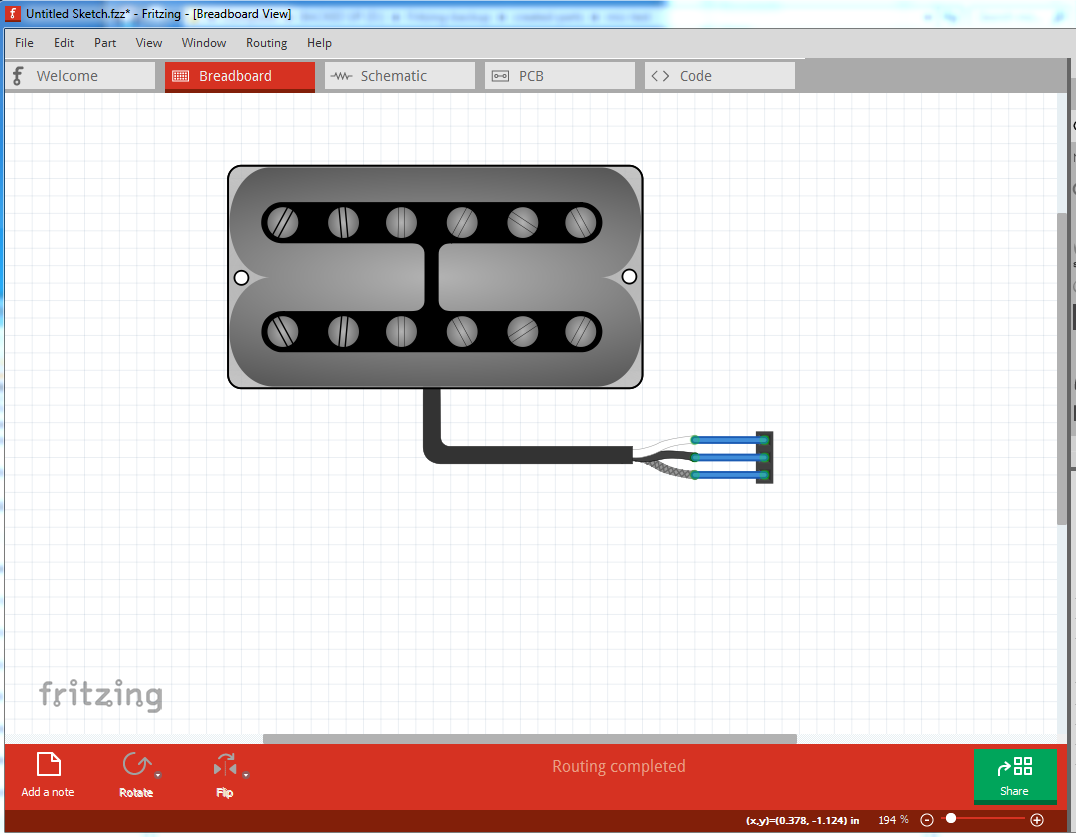
I downloaded the part file and extracted the svg files. Both my standard image view (eog on Fedora 31) and Inkscape (version 1.0) show the breadboard and icon images as the solid black shapes shown in the top screen shot you included. No gradient visible. Examining the svg files directly, I can see gradient definitions and references, but the are not displaying for me. Either my program versions do not handle the gradients, or the svg files got broken by the time that Fritzing part was created.

The gradient definitions are inside of an svg “defs” element. I am fairly sure that nothing inside of that will be used by Fritzing, at least in part files. The reason is that those elements use id tags that need to be referenced in other elements in the image, and a Fritzing document (sketch) is made up of multiple parts, even multiple copies of a single part, each of which has image information. It is non-trivial to automatically merge the defs from multiple image files, and rename all of the references to make them unique. So that the correct definition would be used on each part. Which is probably why (one of the reasons) that the “SVG Tiny” specification excludes gradients, and several other things in the list.

I also ran the part through FritzingCheckPart. It has some complaints, some of which are just warnings, and Fritzing handles the case just fine. Others indicate possible problems when using the part.

The new convention is to use black stroke for pcb silkscreen. You are using white, which is the old standard. Fritzing handles it either way.

The parts definition shows “terminalId” references for all 3 views of connector 0 and connector 1, but they only exist in the pcb svg file. If they are defined for a view, they should exist in the matching image file. Normally terminalId is only useful in the schematic view. It is used there to mark the “snap point” for a wire starting/ending at the connector. It can be used (I think) in breadboard view as well. I do not think it means anything in pcb view.

FritzingPartCheck also complains that terminalID is not defined for connector 2. In general, terminalId should exist for all connectors in schematic view.

The schematic svg has an invalid inkscape style font reference. FritzingPartCheck automatically removes it, And Fritzing probably just ignores it.

The schematic svg is missing the “schematic” layerid specified in the part definition. It is needed for schematic to work properly.

The connector pin circle elements in the pcb view do not have a radius. Fritzing uses that (minus the stroke width) to set the drill hole size. Without it, no hole will be specified for the gerber export used to get pcb boards created.

That looks like a FZ export, and that FZ modified it - FZ usually adds a lot of groups on a export part -. I guess we need the original svg that you are putting into FZ.

EDIT - I just remembered, there are ways of making gradients without gradients so things look curved. Look at the microphone, tilt switch and clear LED in the CORE bin.

hello, I think I will continue creating the parts as before without gradient jajajaja it is easier …

I wanted to clarify that I draw the breadboard svg, in this case, I also did the schematic but the pcb took it from fritzing without modifying anything.
I am new to fritzing and inkscape, I have a lot to learn and these are the first parts I create.

Another issue to clarify is that I would use my parts to create instrument connection diagrams in the breadboard view … the schematic and the pcb would not use it, but I had to add it because fritzing forces to have all 3 types of view.

Thank you for your answers. I will continue creating the parts with solid colors. If you want, today when I am in my house, I send some different parts to see if it has errors, in my fritzing it works very well but I do not know what the requirements are to be able to share the parts and that anyone can use them.

Thank you. google translator is not very good jajaja bye

It is possible to create breadboard only Fritzing parts. Probably not with the built in parts editor, but I do it outside of Fritzing. It just needs the breadboard view svg. The icon view is needed too, but that can just point to the breadboard view when appropriate.

Here is an example breadboard + icon view only part. Unzip it to see the pieces, and to look at what the part definition file (.fzp) contains. It is not large or complicated, especially when the part only has a few connectors.

2-pin-header.fzpz (2.6 KB)

Here is a version of your part with only icon and breadboard views. The definition file was simplified, and the “breadboard” id was added to the svg. The icon is not working. I seem to have messed something up there.

Gretsch Filtertron-test.fzpz (16.7 KB)

I made no attempt to cleanup the gradient information.

Thank you very much for the info, I did not know what could be done that way.
In the .fzp file the change is to delete everything related to schematic and pcb … and the icon uses the same svg as the breadboard.

Can I create a main microphone with this method and then modify it with edit part in fritzing? I mean edit it in order to create the other microphones.
or this would cause problems

To modify the .fzp files, do you use any specific software or directly with the notepad?

(Here I show some images of the graphics that I made, I have others with different connections…
The battery is not mine, but it looks cool)

As mentioned, I do not use the parts editor for creating parts. So I do not know if that would work.

It is reasonable (I do it all the time) to copy an existing fzp file as the base when creating a new part. Any standard text editor (or word processor that will save as plain text) can be used for editing the file. I use Visual Studio Code (for that and a lot of other things), but standard notepad will work fine. You can adjust information in the svg files the same way. That is what I used to add the missing breadboard id.

The zip program is all that is needed to combine the fzp and svg files into a usable fzpz part file. Or anything else that knows how to create a zip “archive” from a set of file. Just need to rename from .zip to .fzpz, if it will not do that automatically.

Because you are probably the only one that needs guitar pickups, and you’re never going to use the SCH or PCB, I suggest you just use a 2 or 3 pin header part, edit that part and only add your BB svg, and then save that part. So long as all views have the same number of pins, and is assigned, it should be fine.

If you want to upload your gradient svg using a different extension, I can see if I can get it to work.

tracking4hpd_8c2ypxr:
okay, i’m going to do some tests … now i understand a little more about how fritzing files works

Old_Grey:
Yes, I started doing that, I took parts like 2,3,4 and 5 pins for Pcb, coil for Schematic and as the main part for breadboard I edited textile stretch sensor because it was the first one I saw that had the mirror option, which is going to help reverse the position of the mics humbuckers.

Here I show you the svg with gradient, if you can do something

Thank you both

Gretsch Filtertron

It needs someone smarter at INK than me :slightly_smiling_face: 
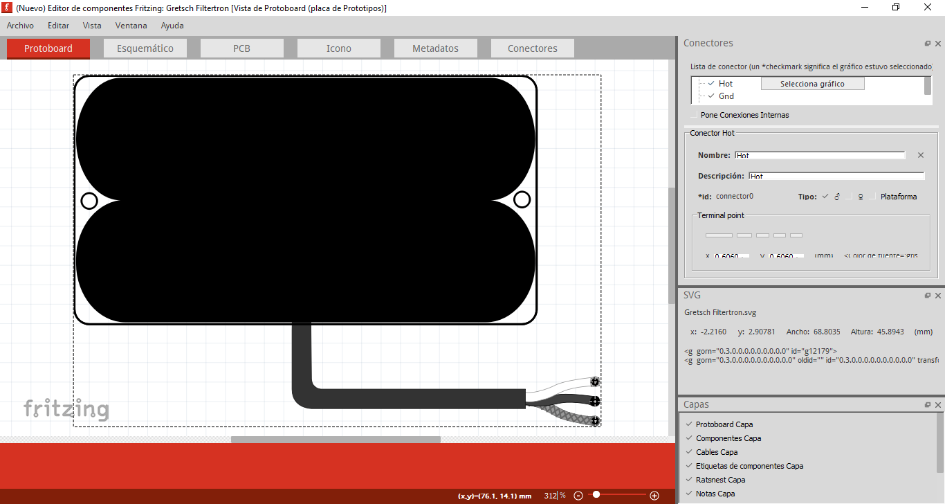
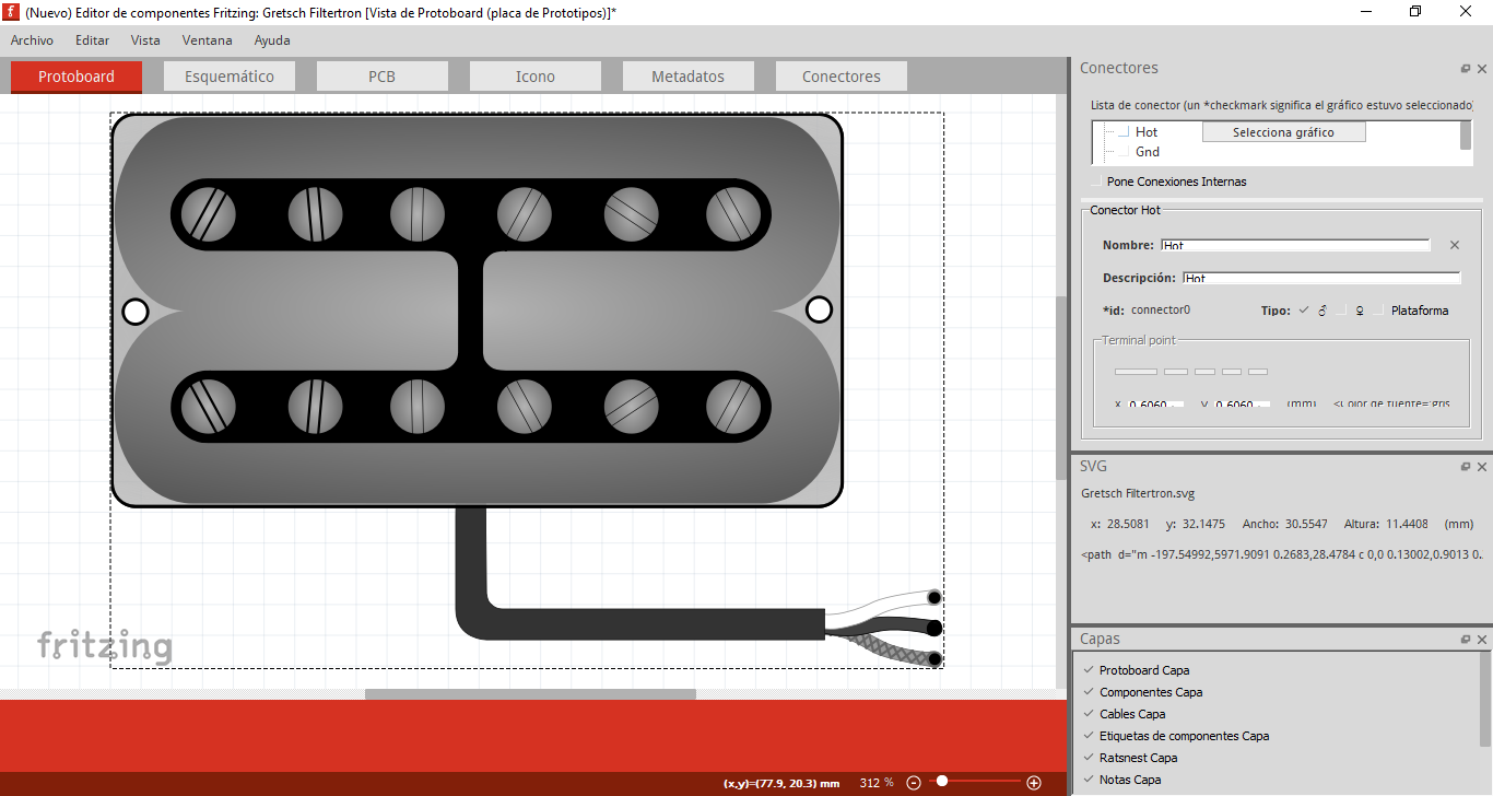
I was thinking the gradient was under the black rectangles, but it looks like FZ deleted the gradients - I think I remember the part export svg having less nodes -.

It appears (as I remembered) that Fritzing will in fact render gradients if you can get them in. It appears parts editor doesn’t support them, but doing them manually (not using parts editor) appears to work (although I don’t necessarily know what gradients are supposed to do). This is your svg above, cleaned up a bit (may not be necessary) and inserted in a part where the gradient appears to be rendering fine:

and the part that creates the above bb image:

mic-test.fzpz (10.5 KB)

If you download the fzpz file and unzip it you will get an ungrouped and regrouped copy of your original svg (with only a single breadboard group) and the three connector pins defined (they were not defined in the original svg. and since I am not using parts editor to set them, they must be defined in the svg itself) Schematic and pcb are from an fc-51 part because it happens to have 3 pins (and are thus wrong for this part, but keep Fritzing happy with the pin definitions in schematic and pcb). The fzp file was modified to refer to the current file names, but the pin descriptions will be wrong. As far as I can see Fritzing is rendering the gradients, but you should look it over and try others to make sure that is true, because as noted I don’t know what the gradients are supposed to do, but it looks the same as what Inkscape renders for the original svg. You can find instructions on creating parts without the parts editor in this tutorial series:

My network connection is still down, so it may take some time for me to reply to questions (I’m posting this from a borrowed machine.) As well the parts checking script (although it didn’t in this case) will sometimes complain (incorrectly) about no layerId because if has found drawing elements in the definitions section of the svg. That is on the list of fixes for the next version.

Peter

hi, ok vanepp thanks for replying …
I’m going to start modifying all the svg and I’m going to create the parts manually.
I will also remove the Pcb and Schematic views as they are not necessary.
I didn’t rename the connectors in inkscape because I saw that creating the parts with the editor generates it by itself. But from what you clarified for me above it is necessary to simplify fritzing.

Thank you all for your time.

Hi, nice job. Do you have alll this guitar parts created. i’m looking for pick ups but i can’t find them.

Hello, excuse me but I had not seen this message …
The parts I was creating were left incomplete, I was busy with other things and did not continue them … I don’t know much about this topic of creating parts and it got complicated, I think I’m going to go back to continue them … I have several parts made in inkscape but not added to fritzing. I know it is a good idea to have these parts to create diagrams … it helps me a lot … at some point I will continue them