for my students i am trying to draw several pictures of batteries and the options, how to connect them together - serial, parallel and serial-parallel.
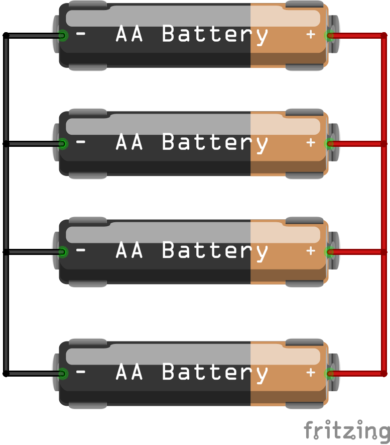
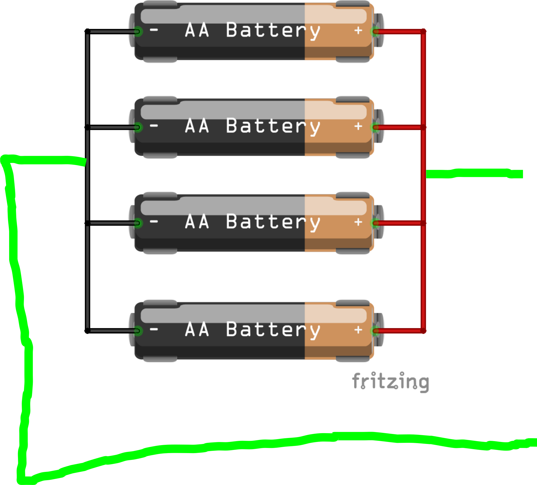
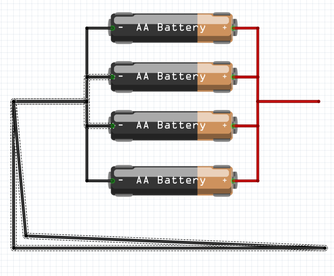
the problem is in the parallel connection of two batteries (and later will be in serial-parallel). my goal is to draw something like this: https://batteryuniversity.com/_img/content/1s4p-copy.jpg i have no problem to interconnect two batteries (interconnecting the same poles together). but when i am trying to create node on both sides of connected battery poles and interconnect it with “floating” wire, i have no success. can you help me please?
the situation is also similar, when drawing schemes for connecting resistors. so that’s nothing special or new.
i was thinking about the following solution just for drawing purposes: to draw a wire and place it over the node without connection, and finally export is as a picture. or to use breadboard for interconnection and then remove it in gimp or whatever bitmap editor.
but if you know the way, how to draw such picture in traditional way, i will appreciate your help.
I’m not seeing your problem. Can you please upload the sketch (the .fzz file) that doesn’t work and I’ll have a look at it. Upload is 7th icon from the left in the reply tool bar.
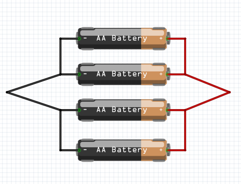
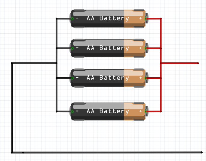
In BB view you can’t connect to the middle of a wire, but if you do like Van and run individual wires from battery to battery and overlap them, it looks like they are connected to the middle of the wire.
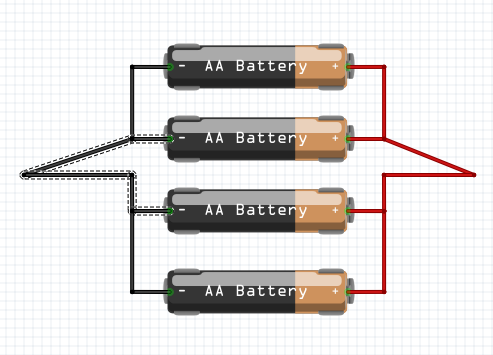
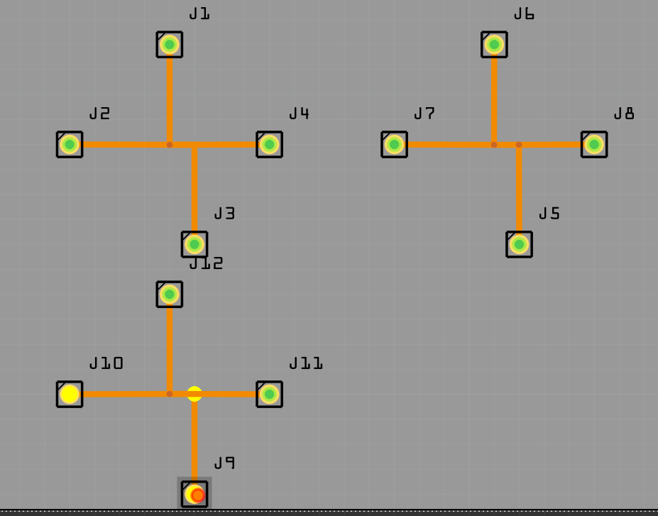
Learn how to do junctions. Either grab a wire in the middle and move it and move it back and it will create a bendpoint, or right-click on the wire and make a bendpoint. Then hold ALT and click on the bendpoint and make a trace from it to the pin. Otherwise you will always be wasting time clicking on pins to see what is connected.
i found this way exactly the same day as you published the solution. i was just curious, if there is some easier solution like “doubling” the wires creating closed circuit. thanks anyway.
mirek
p.s. sorry for delay, but i tried to move on, when i solved my issue
It can be a bit tricky. One way you can achieve it is by using a drawing tool like a vector-based software (e.g., Adobe Illustrator or Inkscape). Draw the batteries and their terminals separately, then overlap the wires and group them. This way, it’ll look like they’re connected without physically touching. It might take some practice, but it should give you the visual you’re looking for. And hey, if you’re into exploring power solutions, check out options like home energy storage systems at https://www.acebattery.com/collection/energy-storage-battery

