After renaming an older design to change the layout and starting from that older design I ran into an overlap problem when running DRC.
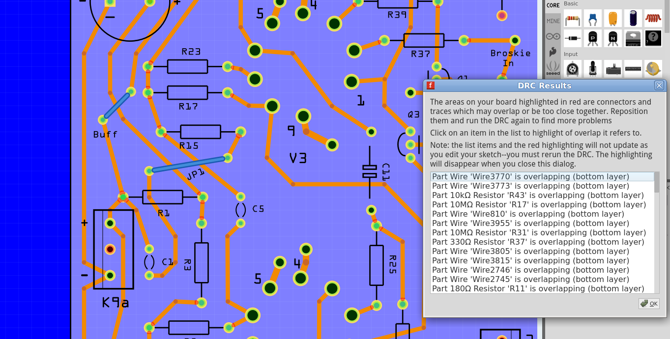
All of a sudden all connections to and from resistors with 600 mil pin spacing have overlap. Used those same resistors in the original design do not show this problem.
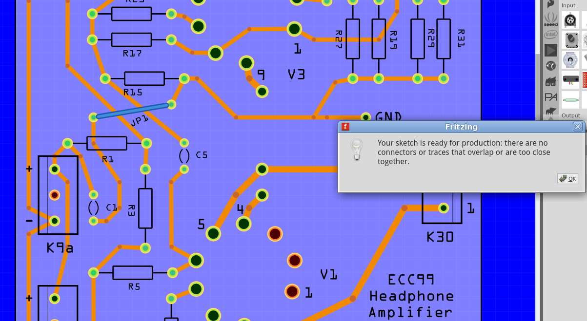
Gave two pictures: one original design same area with no problems and the other picture showing those overlap problems in about same area.
I must have done something stupid here but what?
Upload the two sketch files (the .fzz file) or only the .fzz file where DRC breaks if you are limited to a single upload. It is much easier to find the problem working from the .fzz file than an image.
Peter
ECC99-Amplifier-Mk-1b.fzz (35.3 KB)
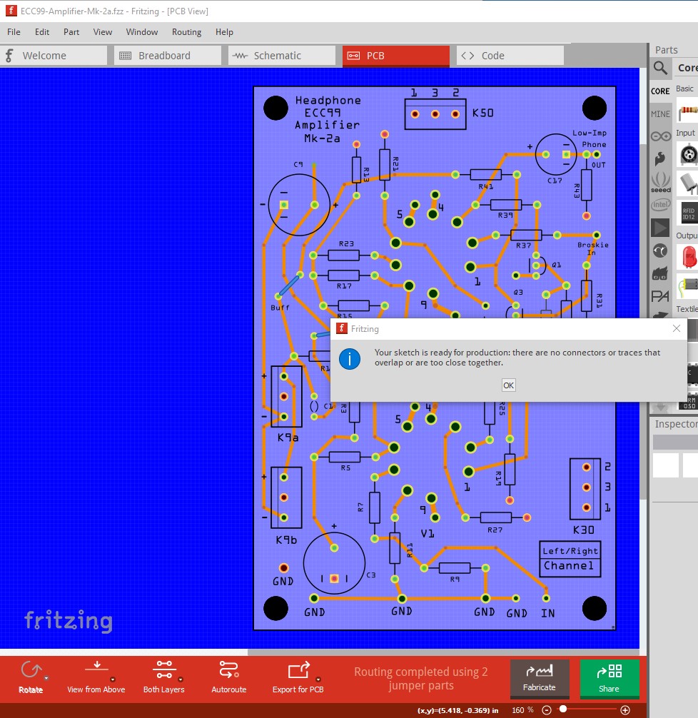
ECC99-Amplifier-Mk-2a.fzz (38.9 KB)
The first file is the original (Mk-1b)
The second file was copied from Mk-1b and renamed Mk-2a. Then after some modifying Mk-2a and running the DRC, those overlap problems started.
The Mk-2a is only partly modified with respect to the Mk-1b.
Hope this helps!
Both work for me on 0.9.6
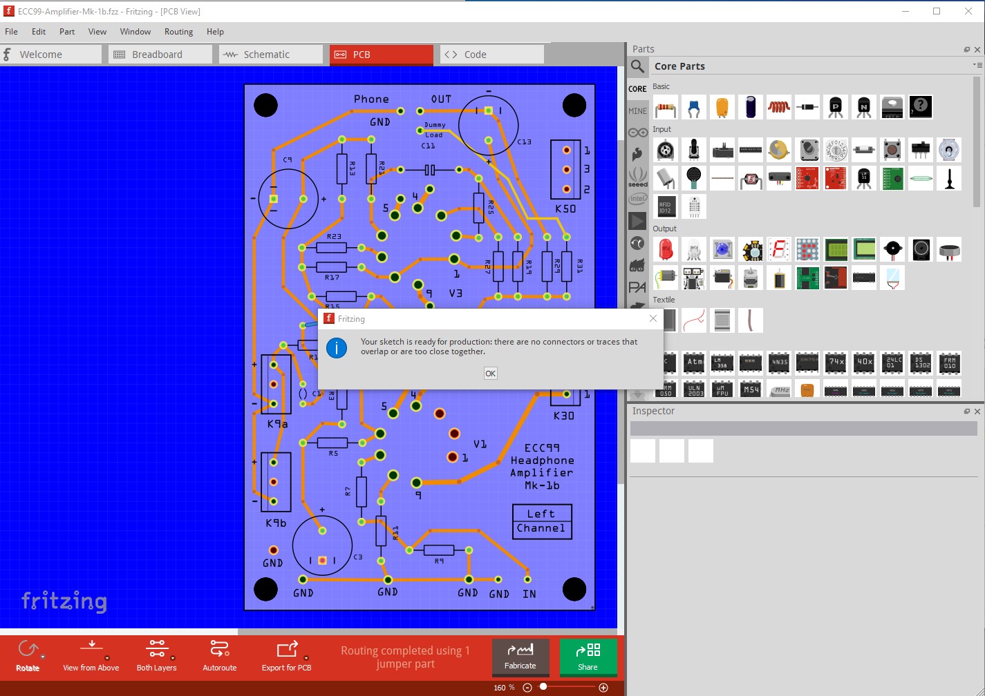
With DRC set to home brew (which should want the widest spacing.) Check the drc settings
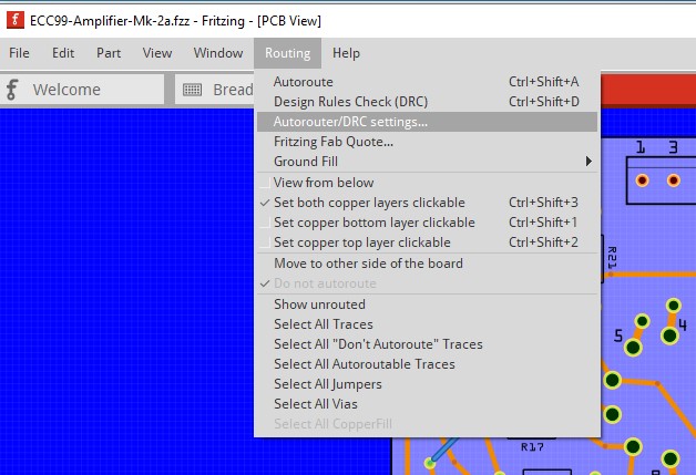
If you have a custom setup for autorouting, that will be used on DRC as well and may be the problem.
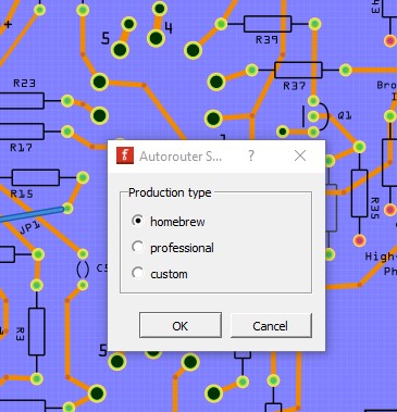
Setting it back to home brew or professional should do the trick.
Peter
Peter, thanks for your suggestions but whatever I do concerning these settings it still gives those stupid overlap problems.
I think something went corrupt in this file so I will start all over again and see where it will go then.
Keep you informed. Never had this kind of (corruption?) problem before.
Since both uploaded fzz files worked for Peter, it does not seem to be a file corruption problem. It could be a difference in the version of Fritzing used, combined with application settings differences. Although my impression is that the settings are all carried in the fzz sketch files, so that they can be different in other sketches without needing to be changed when another sketch is opened.
That was my first thought, changing connections in multiple views can corrupt the routing database but the sketches both load for me on Version 0.9.6 on Win10 and pass DRC fine, so there doesn’t appear to be corruption in the .fzz files. It may be worth trying a reinstall of the Fritzing app in case something in there has been corrupted somehow though. Although if the first file still passes DRC that argues it shouldn’t be Fritzing corruption (maybe.) First time I’ve seen a problem like this, normally DRC here will show the overlaps and we can look at the files to see why.
Peter
Solved the problem !! 
Closely looking to the Mk-2a layout I discoverd at the right part of the layout this:
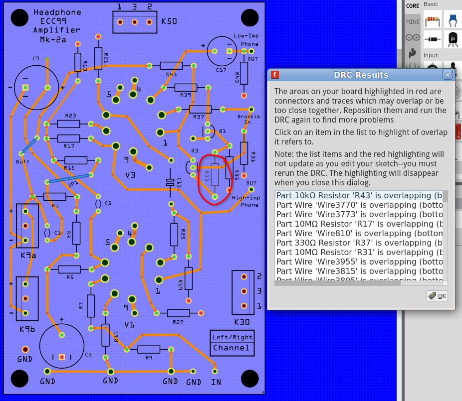
In the red circle that R33 is placed as BOTTOM in stead of the TOP which was my intention. Then I thought : What if…
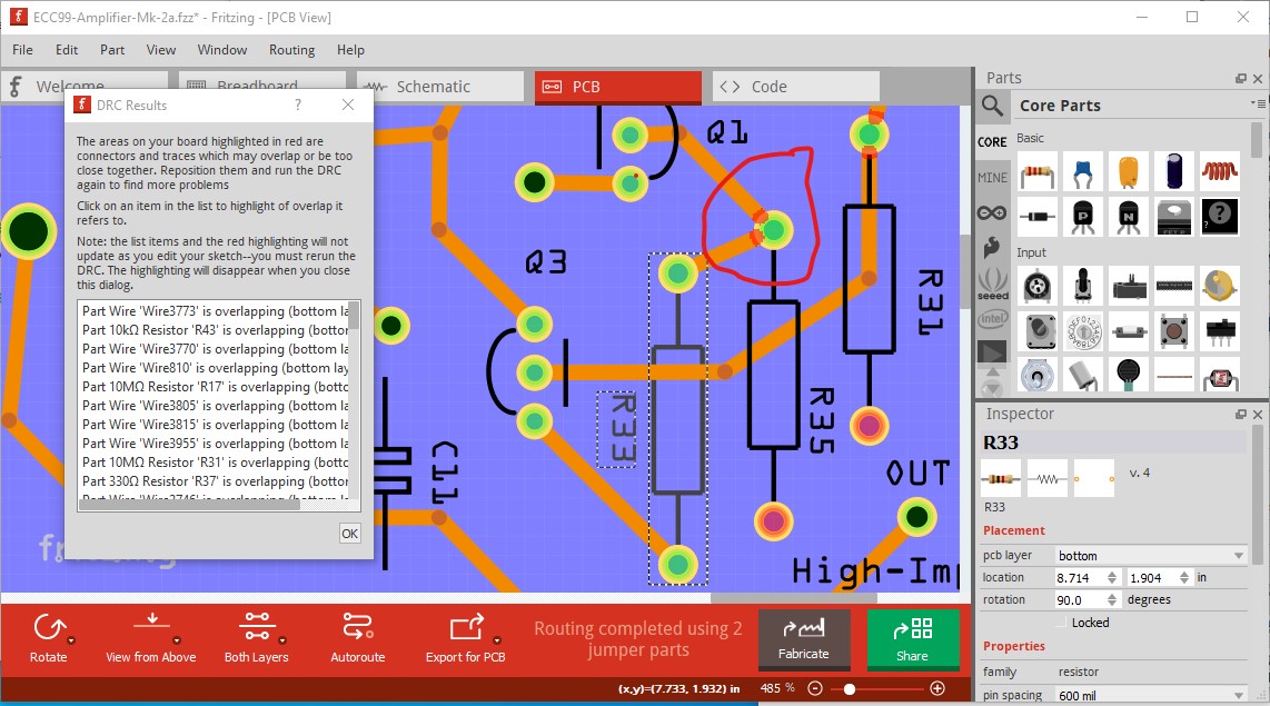
Removed the connections to that resistor, changed it from BOTTOM to TOP , ran
the DRC again and … see picture two:

Leaves me puzzled why you guys do not had that problem because I again downloaded those files from the forum into my test part and still faced that same promlem. So that is mysterious but anyway : problem solved.
On second thoughts: perhaps the fritzing version?
Yes it appears to be Fritzing version. When I load the file under 0.9.3b I get the DRC errors, they must have been fixed in 0.9.6 (I don’t think they were in 0.9.4 although I don’t have a copy loaded currently, there were only a half dozen of so fixes included.)
Peter
I may have just found the cause for this as well. It appears if you have pcb set to bottom layer only and add a new part, Fritzing sets the part to bottom in Inspector. This is certainly not what I expect to happen (although there is an argument that you have specified bottom layer …) so I reported it as a bug. It doesn’t matter for a resistor, but anything like an IC will be a disaster as bottom of the board will reverse the pins if you then (as you likely will) insert it on the top of the board.
Peter
Thanks Peter. Yes, it is a little bit strange that fritzing does not give a warning when
one places a component in the bottom part because this not the usual way to do.
But anyway in the end a positive result when I posted this problem.
Joe.