Optocoupler H11AA1
H11AA1.fzpz (10.9 KB)
Welcome aboard! Your part has a number of problems, mostly in schematic and pcb. In schematic
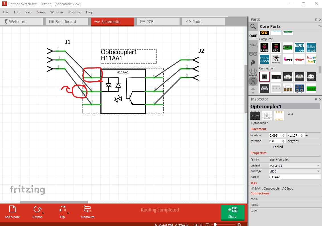
You are lacking valid terminalIds which cause the wires to connect to the center of the pin rather than the end as they should. Then pin 2 is not on the .1in grid as it should be, the three pins should be .1in apart so they fit on the grid correctly. As well you appear to have a bus that should not be present. If I click on pin2
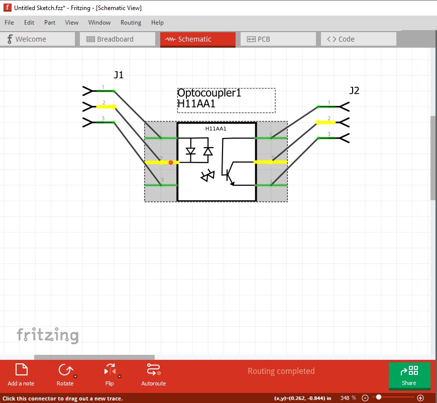
pin5 lights up as well indicating Fritzing thinks there is an internal connection between pins 2 and 5 which there should not be. In pcb there is something wrong with the definition of pin 1. The red square indicates a connector problem and the rats nest line pointing towards the red square instead of pin1 indicates it is on the pin 1 connector definition.

In practice pcb is pretty much entirely wrong and I’m surprised it works as well as it does:
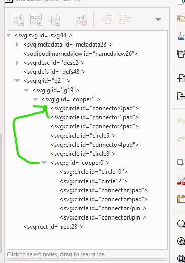
copper0 should be right under copper1 with all the pads below copper0 not mixed as they are. I replaced the pcb svg with one from a generic 6 pin IC which is correct and looks like this:
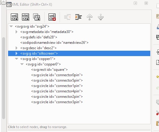
I will also need to change the pads to pins in the fzp file to make this work. Also in the fzp file I deleted the bus definition which is incorrect for this part:
<bus id="internal1">
  <nodeMember connectorId="connector7"/>
  <nodeMember connectorId="connector1"/>
</bus>
Here is a corrected version of your part.
H11AA1-fixed.fzpz (7.3 KB)
Peter
1 Like
thanks, it’s the first component i make.
sorry for my bad english, it’s not my language
You are understandable and that’s whats important. Making parts is complex, and poorly documented as well but it does get easier with practice.
Peter