Could not find this so here it is.
note these are the .56 in high not the .91 in
they support 3.3v and 5v
Could not find this so here it is.
note these are the .56 in high not the .91 in
they support 3.3v and 5v
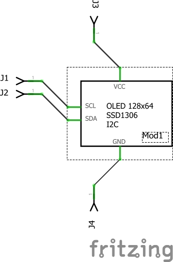
A number of problems. The most visible is that there are no terminalIds and schematic is not aligned to the .1 in grid causing this:
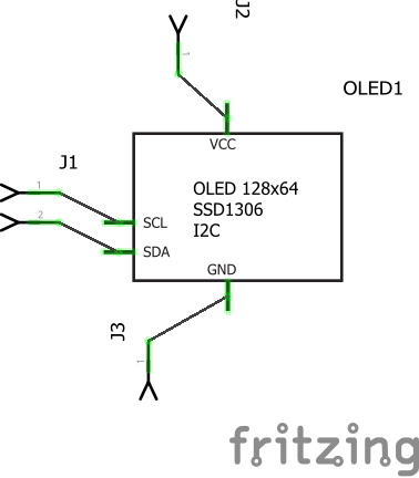
the line terminating in the middle of the connector is caused by no terminalId. With terminalIds added (and alignment corrected) it looks like this:
In addition pins should start at 0 not 1, there wasn’t a silkscreen in pcb and the pins and all svgs were missing layerIds (the only result of that is the part won’t export as an svg). All of this is corrected in this part:
OLED Mono 0.56 inch blue or white-fixed.fzpz (6.4 KB)
Peter
grant you i should have marked the pins on the PCB file but the lines all line up strait for me in the schematic editor.
i borrowed the schematic SVG for the fritzing core files and only edited the text.
Not sure what the difference is to cause that.
mind you this was my 1st fritzing part, i usually use Eagle CAD
You likely needed to (in Inkscape anyway, not sure about the other svg editors) do a File->document properties->resize page to contents. In theory Fritzing is supposed to align to one of the pins, in practice it seems a lot more complex than that. It seems to take an average or something like that. I haven’t figured out exactly what it does, nor been able to figure out how to guarantee alignment even by testing. At some point I’ll need to look at the source to figure it out. Usually doing the resize page to content gets the pins to align to the grid though.
Peter