Hello,im start in project electronic.i have the squematic but i dont know translater to fritzing.could somebody help me please¿
If you have a schematic, then you should start fritzing, then select the components in the schematic (you may have to search for / create some components if they aren’t in fritzing) and then drag them in to schematic view and connect the wires to match the schematic you have. Once that is done you can them place and route breadboard and pcb views if you wish. I don’t think there is anything that will import a schematic from another package if that is what you are asking.
Peter
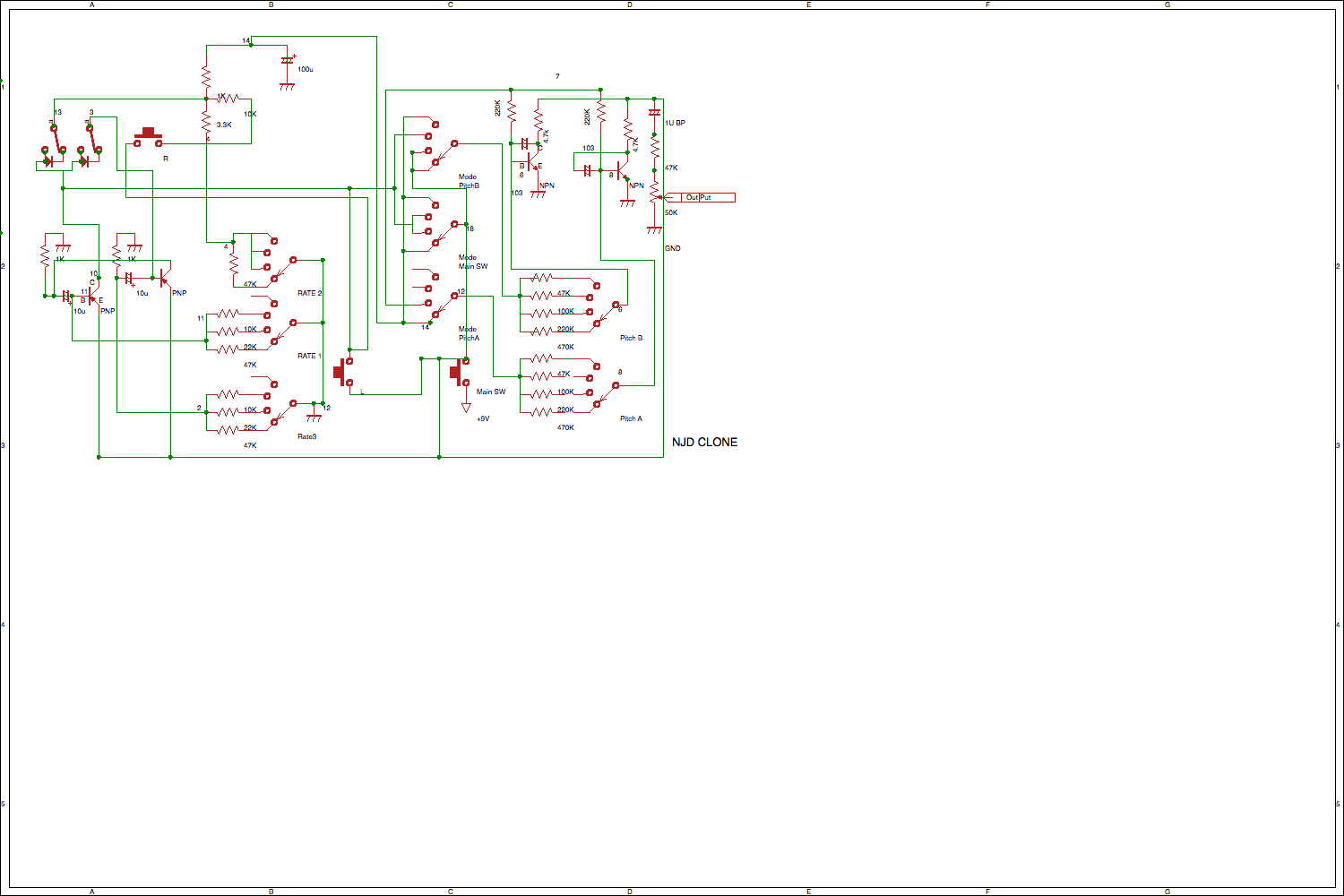
It is mosty standard parts available in core, so it should be fairly easy to make.The only one not in core is the 4 way switches but as luck would have it I made one for someone a while back so you can download that part from here:
as Rotary_Switch_4x1.fzpz and then import that in to fritzing via file->open to get the 4 position switch. If I hadn’t done that then you would need to use google to search to see if someone else had, or make a new part (which is fairly complex). Good luck, and feel free to ask questions if you get stuck. The best bet with a problem is to upload the .fzz file of your sketch here so we can see the problem. To do tht use the upload button (7th from the left) on the reply tool bar.
Peter
Thank you very much peter for the help provided, it has been very useful
The major problem you will have is not knowing that the parts are 100% connected. It might look like it, but you have to be sure.
Pins on parts turn green when connected, and if you click on a pin all pins connected will turn yellow.
Always put a small wire between pins, don’t just put them on top of each other.
If you want a junction right-click on the wire and create a bendpoint, the run the wire from the pin of the part to the created bendpoint. Grab the junction and move it and make sure all the wire move with it. This doesn’t work properly with 4 wire junctions, because there is a bug, but you don’t have any.
Be meticulous, and check and check again.
EDIT
Also small dots on a wire is a non connected bendpoint, and a large dot is a junction.
I used the word wire, but maybe trace would be better for the SCH view.
Hi there,
Does anyone knows if this schematics works?
I’ve allready tried to follow schematics founds on here and there and it wasn’t succesfull…
Thanks guys!
No, I at least don’t know if it works or not (nor for that matter what it is supposed to do!). I do notice that the transistors are only specified as npn or pnp, no part numbers so it may depend on you using suitable transistors as the bias levels may be important. As well it is unclear what the units on the non electrolytic caps are. Is “100” 100pf 100nf or something else (that would affect function I expect). Perhaps the original poster will share whether it worked for him and what values he used if so.
Peter