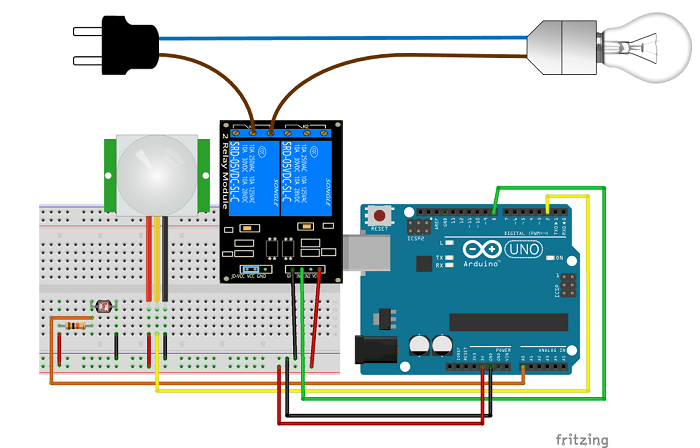
Night Security Light Working Problem

int relay = 8;
volatile byte relayState = LOW;

int PIRInterrupt = 2;

// LDR pin is connected to Analog 0
int LDRPin = A0;
// LDR value is stored on LDR reading
int LDRReading;
// LDR Threshold value
int LDRThreshold = 300;

// Timer Variables
long lastDebounceTime = 0;
long debounceDelay = 10000;

void setup() {
// Pin for relay module set as output
pinMode(relay, OUTPUT);
digitalWrite(relay, HIGH);
// PIR motion sensor set as an input
pinMode(PIRInterrupt, INPUT);

attachInterrupt(digitalPinToInterrupt(PIRInterrupt), detectMotion, RISING);
// Serial communication for debugging purposes
Serial.begin(9600);
}

void loop() {
// If 10 seconds have passed, the relay is turned off
if((millis() - lastDebounceTime) > debounceDelay && relayState == HIGH){
digitalWrite(relay, HIGH);
relayState = LOW;
Serial.println(“OFF”);
}
delay(50);
}

void detectMotion() {
Serial.println(“Motion”);
LDRReading = analogRead(LDRPin);

if(LDRReading > LDRThreshold){
if(relayState == LOW){
digitalWrite(relay, LOW);
}
relayState = HIGH;
Serial.println(“ON”);
lastDebounceTime = millis();
}
}
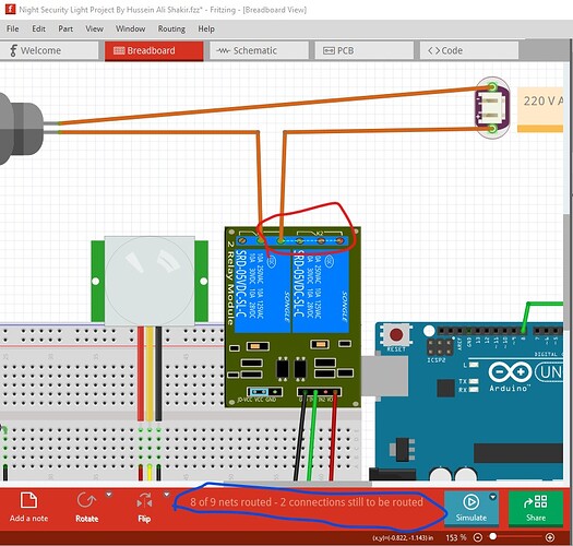
I applied the code & cct diagram as in the below link but the concept of night security light did not work. Plz, I need a help for this project.

@vanepp Plz, your valuable suggestion for that

As I said you need to upload the .fzz file of the sketch in Fritzing to do much with this. The most likely answer is that something is wired wrong but it is impossible to tell without the sketch that the wiring was made from. The “schematic” in the project actually looks like an edited Fritzing post (likely because the power plug and bulb aren’t typical Fritzng parts although both are available on the net.) With a sketch it is possible to tell if the breadboard wiring is incorrect (by populating the schematic view that is populated by default from the sketch and making sure it matches the code) but without that it is impossible to do much. You could also double check the wiring (assuming that the “schematic” in the post is correct of course!) against the supplied image to make sure all the wires are correct, but a sketch is a better bet.

Peter

Night Security Light Project By Hussein Ali Shakir.fzz (41.5 KB)

Find this above fritzing file for your request & the below is the code
int relay = 8;
volatile byte relayState = LOW;

int PIRInterrupt = 2;

// LDR pin is connected to Analog 0
int LDRPin = A0;
// LDR value is stored on LDR reading
int LDRReading;
// LDR Threshold value
int LDRThreshold = 300;

// Timer Variables
long lastDebounceTime = 0;
long debounceDelay = 10000;

void setup() {
// Pin for relay module set as output
pinMode(relay, OUTPUT);
digitalWrite(relay, HIGH);
// PIR motion sensor set as an input
pinMode(PIRInterrupt, INPUT);

attachInterrupt(digitalPinToInterrupt(PIRInterrupt), detectMotion, RISING);
// Serial communication for debugging purposes
Serial.begin(9600);
}

void loop() {
// If 10 seconds have passed, the relay is turned off
if((millis() - lastDebounceTime) > debounceDelay && relayState == HIGH){
digitalWrite(relay, HIGH);
relayState = LOW;
Serial.println(“OFF”);
}
delay(50);
}

void detectMotion() {
Serial.println(“Motion”);
LDRReading = analogRead(LDRPin);

if(LDRReading > LDRThreshold){
if(relayState == LOW){
digitalWrite(relay, LOW);
}
relayState = HIGH;
Serial.println(“ON”);
lastDebounceTime = millis();
}
}
@vanepp your support plz

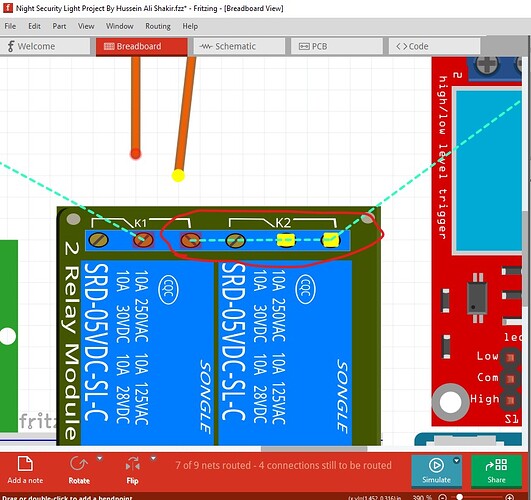
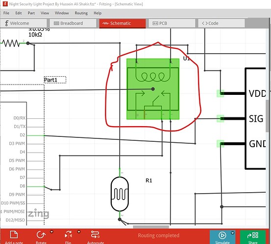
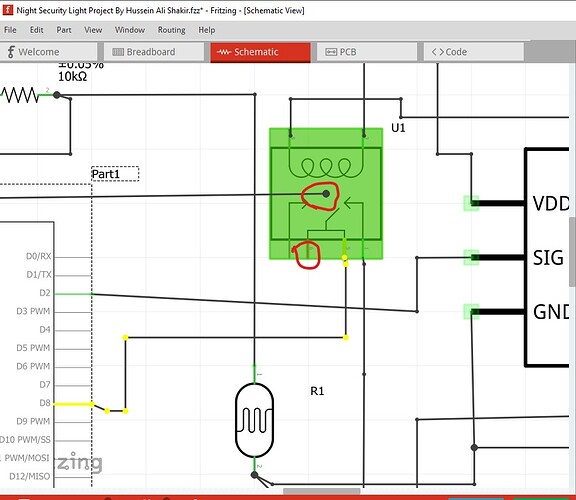
You have a variety of problems. The main one is the relay part is broken, but there are a variety of other issues as well. Here (circled in red) there is a missing connection (indicated by the rats nest line between the relay pins) which is caused by the relay part being broken. That shouldn’t break the actual circuit assuming the physical relay board works correctly though.

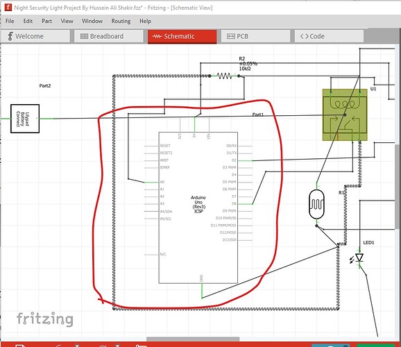
The green rectangle around the relay indicates the part is configured and thus broken. To fix that I replaced it with a mostly identical but working relay part. If you need this exact relay part I can correct the current part so it works but I didn’t in this case.

one indication that the part is broken is that the two common wires don’t connect to each other (the second relay is also missing.) When I clicked on the pad lit yellow the pad connected to it should have also lit up yellow.

There is a short across the second relay terminals (which won’t matter in this case as it isn’t used but will confuse routing!)

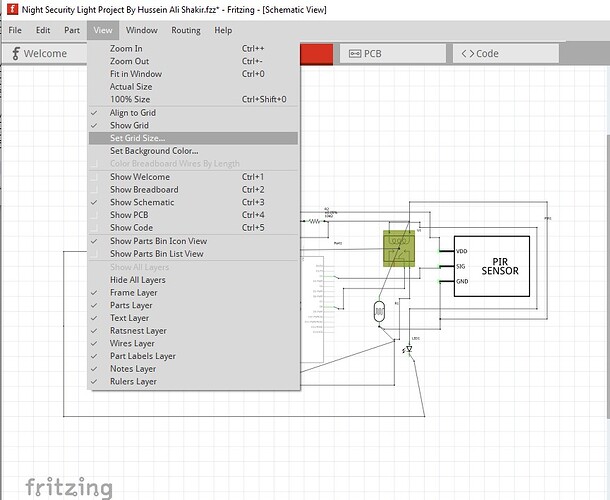
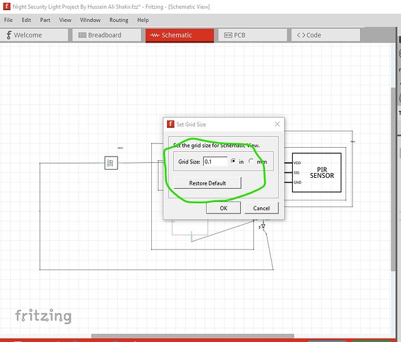
the scale in schematic is set wrong. If I show the grid size

It is set to 0.295276in it should be the default 0.1in so click restore default to correct that.

clicking OK changes the schematic grid size and then moving the various parts aligns them correctly to the grid.

The pins on the Arduino should align with the grid but with the odd grid size they do not.

With the grid size changed and the relay part substituted the schematic now appears correct and the circuit should work, although if you wired it as indicated the original circuit should also work I expect. This sketch has the indicated changes and the new relay part in it.

Night Security Light Project By Hussein Ali Shakir-fixed.fzz (45.1 KB)

Peter

Thanks a lot Peter for your deep clarification & support in fritzing. So, what do you think practically problem with the real cct shown in pic plz. As I connect them accurately as it is but did not give the concept of night security light.
Note the below is new code uploaded but still issue persists.

const int relayPin = 8; // Relay connected to pin 8
volatile bool relayState = LOW;

const int pirPin = 2; // PIR sensor connected to pin 2
const int ldrPin = A0; // LDR connected to analog pin A0

const int ldrThreshold = 300; // LDR threshold for darkness
const unsigned long debounceDelay = 10000; // 10 seconds delay

unsigned long lastDebounceTime = 0;

void setup() {
pinMode(relayPin, OUTPUT);
pinMode(pirPin, INPUT);

digitalWrite(relayPin, HIGH); // Relay off initially

attachInterrupt(digitalPinToInterrupt(pirPin), detectMotion, RISING);

Serial.begin(9600);
}

void loop() {
unsigned long currentMillis = millis();

if (relayState == HIGH && (currentMillis - lastDebounceTime) > debounceDelay) {
turnOffRelay();
}

delay(50); // Short delay to prevent excessive CPU usage
}

void detectMotion() {
Serial.println(“Motion detected”);

int ldrValue = analogRead(ldrPin);

if (ldrValue > ldrThreshold && relayState == LOW) {
turnOnRelay();
}

lastDebounceTime = millis(); // Reset the debounce timer
}

void turnOnRelay() {
digitalWrite(relayPin, LOW); // Turn the relay on
relayState = HIGH;
Serial.println(“Relay ON”);
}

void turnOffRelay() {
digitalWrite(relayPin, HIGH); // Turn the relay off
relayState = LOW;
Serial.println(“Relay OFF”);
}

Thanks in advance

It is hard to say because I don’t know what the code is supposed to do. The I/O pin definitions look correct to me, they appear to match the physical connections in the sketch so if the original code worked then yours should as well. Thats about as far as I can say.

Peter

1 Like