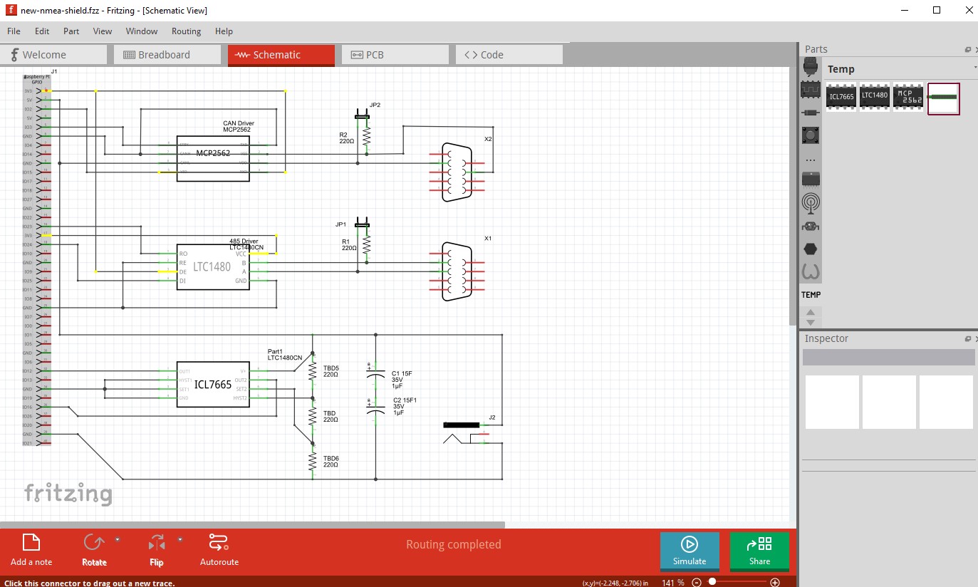
So, am experimenting with the goal to create a physical card. I have a schema which is good enough to test. There is also BB and PCB views which looks sound to newbie me.
However, there are some awkward rastnets lines. I presume these means that I have something wrong, and try to figure out what. Doing so, each line has a tooltip like “Wire 50564” which looks promising.
Now, is there a way to locate a wire if I have such an id at hand?
Your best bet is to post the sketch file (the .fzz file, upload is 7th icon from the left in the reply menu) so we can see what is happening. If you have unexpected rats nest lines there are two possibilities: 1) you have connected something incorrectly in another view (which will reflect in to the other 2 views), 2) you have managed to tickle a bug that corrupts the routing database (in which case you need to delete all traces in all views and remake the sketch, completing one view first and then route the rats nest lines in the other 2 views.
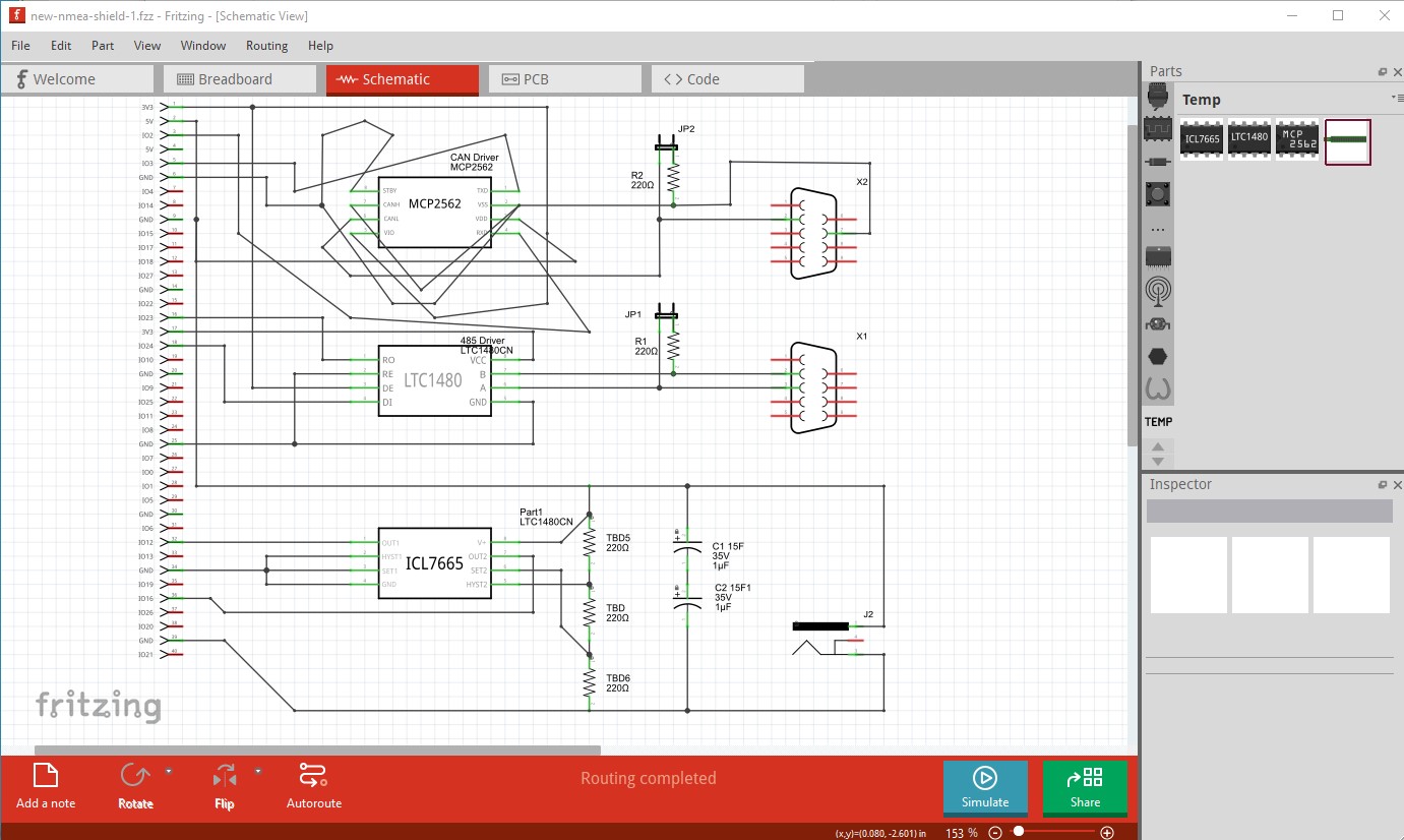
I guess reverting to a cleaner state make a lot of sense in this situation. I did remove all traces in all views and re-constructed the schema. Looking at the situation now it’s obvious that the rastnets lines for the PCB is wrong, for example the bottom-left corner with capacitors and a resistance bridge.
Feeling dumb, my gut feeling is that I’m making some stupid mistake. Enclosing current state
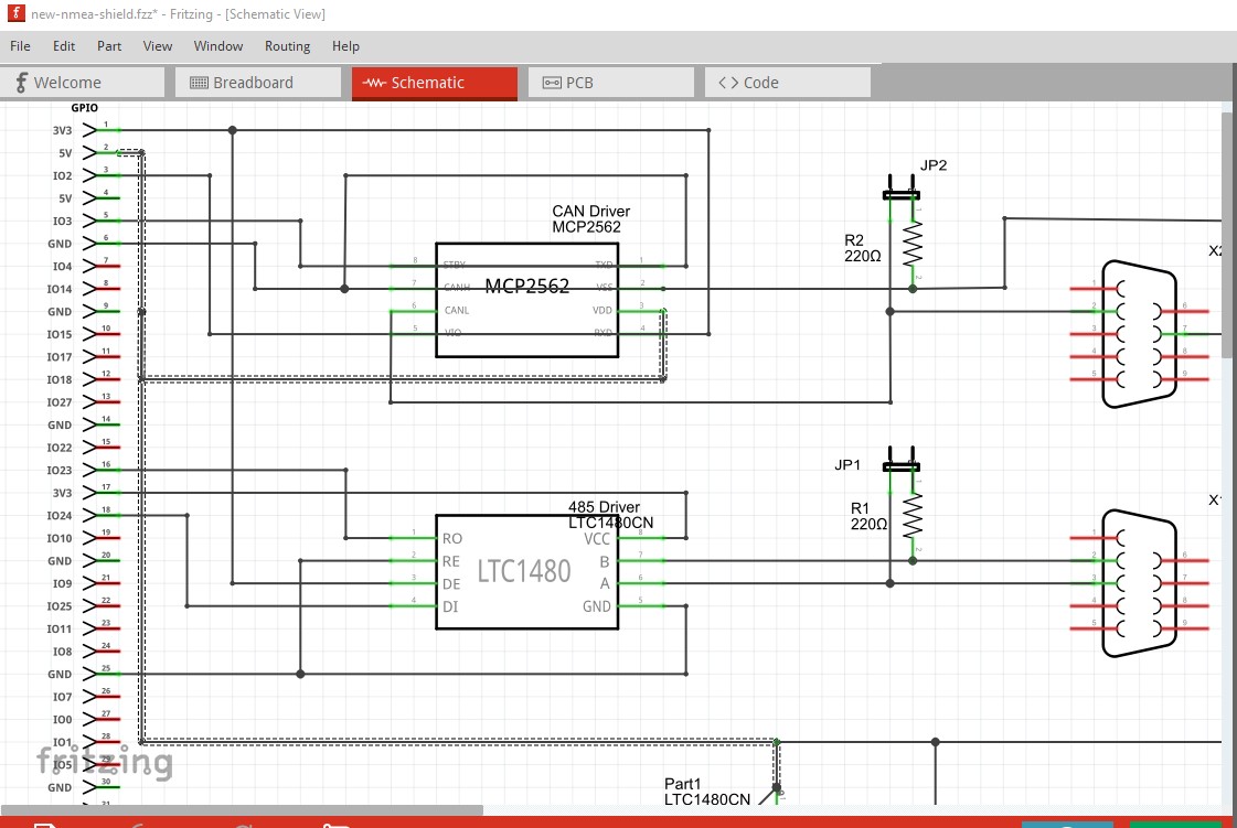
EDIT: hm… When re-loading whayt I uploaded, the connections for MCP2562 in the schema are suddenly a mess. I think it’s obvious what I ment from the beginning, though. Something is very broken here…
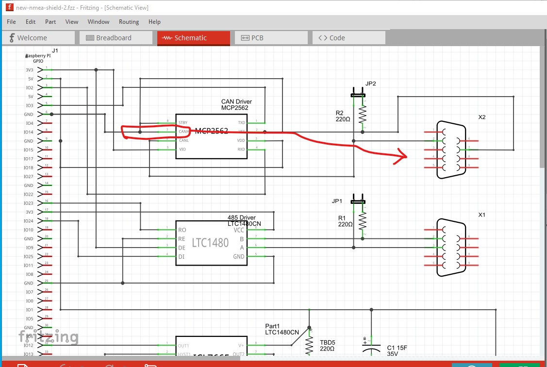
Here I clicked on the top 3.3V connector on the RPI connector, all connections in that net are then highlighted in yellow. It appears to go where it should, however on the MCP2562 the routing is odd. It looks like (but actually is not) that the wire should be shorting rxd on the other side of the IC. Clicking on the wires one at a time and dragging them sorts out the connections:
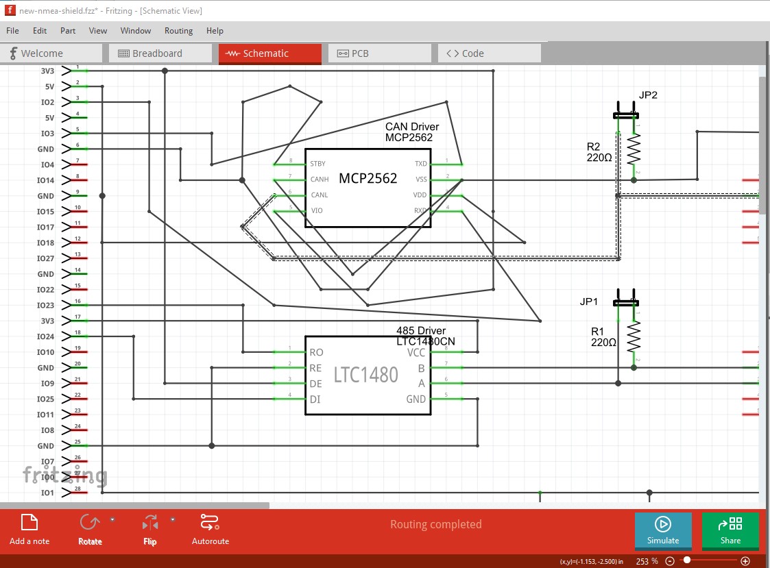
doing all the rest (in somewhat odd order to make it clear where the connections go) appears to fix everything (assuming the connections are as you expect them.) I don’t know why the routing changed on storage, I don’t think I have seen a previous case of this (and it may indicate a bug has been introduced.) For me saving the file then reloading it worked as expected:
then I corrected all the odd traces, but I expect there is still an error as the CANH pin I expect should go to the DB9 not to ground as it is currently.
New users have a way of doing things which leads to results more seasoned users don’t get. I’m the newbie here, stressing the system in ways I probably can’t reproduce any more.
Anyway, removing all traces and wires obviously just was not enough to reset all state – my initial try seems to be broken beyond repair.
I started all over with a blank project, and this time it seems to work. There was one problem: I connected the resistance bridge directly in the breadboard, without some space for upcoming wires. Fritzing was not happy about this, the wiring basically broke down.
However, after fixing this everything looks fine in my end. Again: thanks for all your help. Learned a lot from your replies.