Newbie: first circuit, thoughs?

hi to all.
I’m totally new to Fritzing (and to arduino).
I’m trying to build a very simple NodeMCU multi-probes temperature device.

In reality, i did it again on a breadboard, I would like to replicate the same on fritzing to build a printable PCB (jlcpcb i think)

I have some issue with autorouting on Schema and PCB, but let’s start step by step, do you thinkg this breadboard would work ?

It’s very simple: a nodemcu, a DC power jack (5v, but i’ll add more parts later), 6 temperature probes connected with a JST connector. Each JST has one pin to the ground, one pin to the +5V and 1 pin connected to a 4.7kohm resistor and then to the 5V

What type of temperature sensors are you using? There are multiple variations that have different requirements on how they are connected to the controller board. The layout you used only works if the sensors are 1 wire protocol devices. Visually, that looks like a 220 ohm pullup resistor, not the 4.7K you put in the post.

The 5V input is fine to power the NodeMcu board (at the VIN pin), but your layout is also using that to power the sensors, which implies that the data line (through that pull up resistor) is also 5V. NodeMcu is a 3.3V device. My quick search did not find any information to say that it was also 5V safe for the data pins. You probably need a level converter. Which might be as simple as a voltage divider and a transistor.

When asking this type of question, it helps to provided the actual Fritzing sketch file. That way some of the questions can be answer by looking at the actual part in the document.

Yes, sorry for the resistor, it was a mistake, the correct one is 4.7kohm

Im using a bounch of DS18B20 in parasite mode, the breadboard shown is with the old wiring in normal mode. Parasite mode simplify the wiring a lot.

For the power: i have a 12v power supply, then i’ll put a buck converter for 3.3v. biggest issue is: as i would like to share this design as much as possibile with another 2 boards that needs a 5v and 12v rispectively, what do you suggest? I need 3 different buck converter?

Something more simple than a buck converter? Tension regulater are way too hot

One possible simplification. The information I have says the DS18B20 works from 3.0 to 5.0 volts. If the 3.3V line on the NodeMcu can provide enough power, run the sensors from that instead of from the 5V input used to feed VIN. That will get the sensor data line to the proper 3.3V.

I have seen some information that says parasite mode can be trickier to get working reliably. I looked at it (with those sensors actually) for one project, but for my case there was no real benefit.

If you can run the sensors from 3.3V on the node mcu, you can ‘share’ the 5V with this. 12V is going need separate power. If this is going to be physically connected, the main power can be 12V, with a 5V buck converter for VIN here and the other boards, and 3.3V only supplied to the sensors by the NodeMcu board. Not really enough information to say that will all work.

In parasite i’ve tested 5 sensors at the same time (daisy chained) with about 2 hours with no issue
Today i’ll try with 10, the maximum i have to support

But i had a lot of issue with autorouting, both in schema and PCB, the autorouting makes a lot of wrong connections (like connecting all sensors pins together, the gnd to 3v and so on, thats why i’ve posted the breadboard, just to have a confirm that wires are ok)

We can not tell if the wires are really correct just from an image of the breadboard view. Those “wrong connections” can be from the (sensor) part having an error in which pin is ground and vcc on the schematic versus on the breadboard view. It can also be from a crossed wire on the breadboard view, even if that was later corrected. People have seen errors like that, where Fritzing will “remember” a connection that was later changed. This issues tends to get worse if connections are created in multiple views, instead of everything done first on one view, then just filling in wires to match the ratsnest wires in the other views. If the problem started from the last cause, deleting all wires, in all views, then recreating in just one view can fix things.

Again, the full sketch file is needed to start doing anything more than guess. You said “autorouting”, which in frtizing is something different than what your latest description implies. I think you meant that the ratsnest wires in the other views are not going where you expect. That is not autorouting. Autorouting is a tool to layout the traces on a pcb, so that they do no conflict (cross) on the same side of board. It often does not do a very good job, but is quite separate from where the ratenest wires/lines are placed by Fritzing.

EDIT: since the breadboard view of those sensors are symmetrical, it could also be that one or more have been flipped horizontally, which would cause ground and vcc to be reversed.

Symmetrical… Are you referring to the sensor jack (in green)? They are not symmetrical, there is a PIN on the top that is a little bit on the right side and there is a white circle on the left, in the middle

It indeed looks correct, but as noted there are a lot of things that could be wrong that won’t show in an image of breadboard view but will appear if we have the .fzz file to download and examine in Fritzing. For instance clicking on any pin will light all pins that are connected to it in yellow which will point out where a connection isn’t correct or hasn’t connected correctly. As well hovering over the pin will produce the pin number which may be incorrectly connected in another view (and won’t show in an image file.) I don’t particularly see anything that looks like that, but without the sketch I can’t try it to be sure either (not that I will necessarily be looking too quickly as I’m having connectivity issues, but the other folks here can also do it if they have the sketch …) Your best bet is to always post the sketch (the .fzz file) or the part (the fzpz file) when you have a problem. With those files a number of us can trouble shoot problems, without them you get guesses like this from incomplete information.

Peter

I’ve posted the project. It’s just a test.
temperature.fzz (88.3 KB)

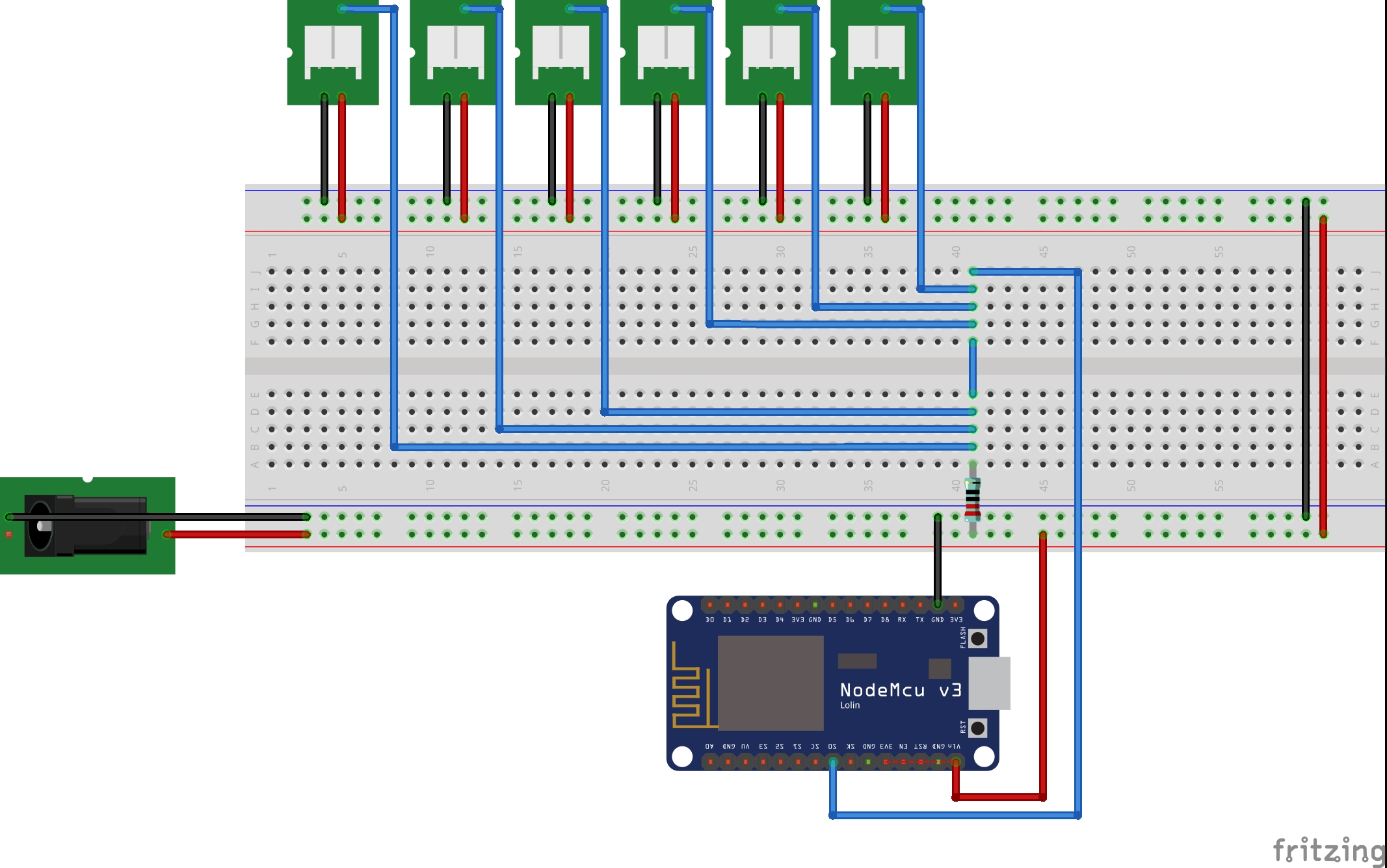
Since the temperature sensor connectors used are all just jumpers / headers, I can not confirm that the power, ground, and data lines are being connected to the right pins when the sensors are actually attached. I can say that the connections are consistent, with the 3 lines going to the same pin of every jumper on the breadboard view.

When Initially loading the sketch file, I confirmed there is a wiring error someplace, because, on breadboard view, clicking (and holding) on one of the power or ground lines high lighted all of both the power and ground connections and breadboard rails. Fritzing sees them shorted together.

They are still shorted together after all of the wires in schematic view are deleted (Routing menu, select all traces, delete). Restoring those traces (undo), and doing the same in the pcb view also shows that power ground are shorted. Deleting all traces on both the schematic and pcb views gets rid of the short.

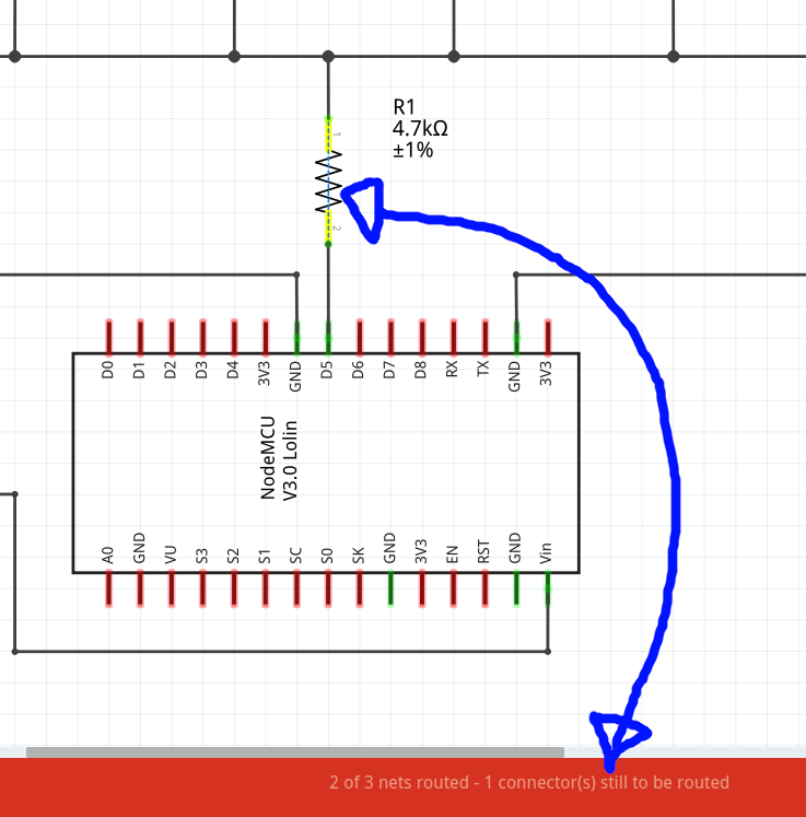
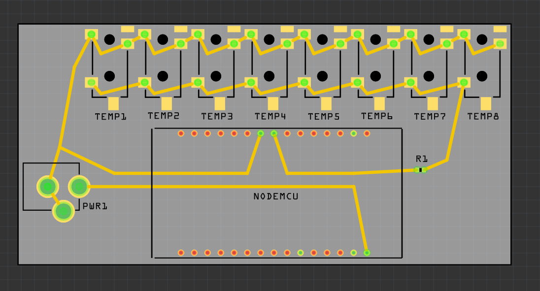
Hovering the mouse over the first (left) BB sensor connection shows that it is JP1. Hover over the connection point with the black wire, which is connected (through the breadboard rail) to NodeMcu GND, show that it is pin 1. Going to the schematic view and hovering the mouse over JP1, and the connection labeled one, shows that is also pin 1. Following the trace from that pin (down, right, down, right) leads to NodeMCU Vin. Not ground. Same thing on pcb view. Starting from JP1, pin 1, the trace leads to Vin. Not ground.

So either both schematic and pcb have the power and ground reversed, or the breadboard view does. Without knowing which lead of the actual sensor is connected to each pin of the header, there is no way to tell which is right or wrong.

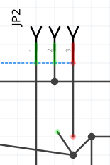
There are other problems, at least on schematic view. JP2, pin 3 is shown in red. That means it is not actually connected. The trace looks like it goes there, but it does not actually connect to the rest of the circuit. The problem is that the trace coming from pin 3 does not connect where looks like. This can be seen by moving the node where the traces appear to join, discovering what looks like another join/bend point, and attempting to move that as well. Which discovers that the 2 traces do not actually connect.

jp2

Schematic and Breadboard are inconsistent another way. On breadboard view the sensor data lines are connecting to NodeMCU pin SO. On schematic (and PCB) view, they connect to D1.

The ratsnest wires (dashed lines) on each view provide hints of these problems. A ratsnest wire is shown on a view when one of the OTHER views has an actual wire/trace between the pins that does not exist on the current view.

bb-rats

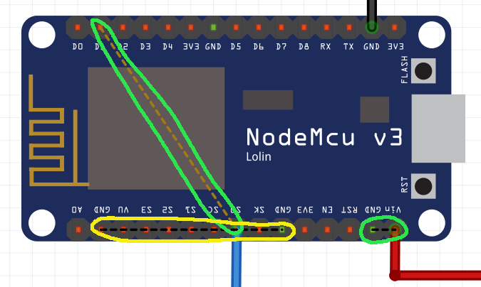
The yellow circle ratsnest above is in indication of an error in the NodeMCU part itself. The Ground pins are not connected internally.

bb-pwr-rats

The circled BB ratsnest above indicates another problem. Details on schematic view.

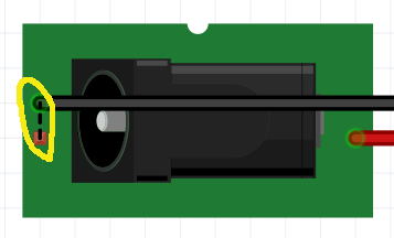
The ratsnest wire between pin 3s of JP1 and JP2 is another indication of the broken connection described above. The yellow circle on the PWR1 part shows the reason for the matching one on the BB view. There are 3 connection pins. 2 of them form a switch that is open or closed depending whether a plug is in the socket or not. On schematic view, you are connecting to the pin that is open when the power is plugged in. The ground connection should be to the bottom connection.

Going back to the initial tests, on BB view, deleting all of the wire gets rid of the power to ground shorts on the other views. As said above, need to know which sensor lead goes to which header pin to tell which is correct.

Thank you for the deep review, greatly apreciated.
I did some changes:
temperature.fzz (91.8 KB)

One issue i had is to properly “detect” the 3.5mm jack orientation on PCB, the part i’ve used, are shown revesed in any online store, so I had to reverse the whole design. Why Fritzing is showing the part upside-down ?

When the design is ok, i would like to improve by using SMD components and, if possible, make a BOM list to provide to an online fab to get a simple PCB with all components (presoldered, if possible).

It’s just a test, but let’s do this step by step.

Another question: fritzing is saying the a line crossing the resistor, is broken. That’s true, because the resistor must close the circuit. Why fritzing is complaining about this ? Doens’t detect the resistor ?

The wiring on the sensor cable is not important, i have to solder the jack plug on my own so i’ll do based on my design. What I would like to is to keep the gnd and sleeve connected together (i’m using parasite mode) even in the cable, so the only real pin is the left one that has to go to D5 on NodeMCU. The other two are joined together

In BB view pin 1 is on the NodeMcu side, and in SCH pin 0 of the resistor is on NodeMcu. Just flip it around in SCH.

I’ve flipped the resistor in schema view, now fritzing is happy :smiley:

Not that it matters, but there is a link missing between the pins on the DC jack in BB view.
I think you have to move the 3.5 audio’s to the edge or it might be hard to plug them in.

Before getting this made make sure you print the PCB on paper and that the parts fit on it. I would even gerber check it.

Something like this ?

(i’ve connected the missing pin in BB)

R1 is supposed to be a “PULLUP” resistor. That is, D5 should connect directly to the sensor data lines, and the resistor goes from that line to power. Since the NodeMCU is a 3.3 device, “power” is also 3.3V. See “Powering the DS18B20” on page 5 of the datasheet and have a close look at the associated figure 6. For your purposes, Vpu in that is the 3.3V that NodeMCU runs at, not the 5V at Vin. As long as the data pin can “source” 1.5mA, the added switch to power during temperature conversions is not needed.

Here is my take on the sketch document.
temperature.fzz (37.3 KB)

Fritzing is going to show the power jack however the part has been defined. That part is from sparkfun, and will have been designed to match their part. I do not know what you mean by “upside down” it looks correct to me, compared to the breakout board image and connectors in breadboard view. Power on the end, with the ground and gndbreak pin in middle and edge, and the open end pointed away, which would be off board so the plug will fit.

If you mean it was rotated 180 degrees on pcb view when initially placed, that is somewhat random. Fritzing does not have any information about which way it should be oriented. There is no intent to force the different views to be lined up the same way. Just because the power jack is on the left, facing left, in breadboard view does not mean it will be the same on the pcb.

thank you so much it helped me alot…