To me, the DB9 Male Connector part in the core library looks broken in some respects.
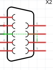
The obvious is that although the DB9 male connector has a well established numbering scheme the part does not follow this. Notably, pin 2 and 3 is Rx and Tx data, which something entirely different in part’s scheme.
Modifying these labels is trivial, though, A bigger problem for me is the PCB view which basically looks upside-down with what should be top-left corner (pin 1/DCD) in bottom-right.
Suppose I could live with the labels after making some kind of translation table. However, I’m just so unsure about the PCB generated here. To me, the whole things looks shaky.
I suppose I miss something simple? Any clue, out there?