New project with Raspberry Pi Pico

Hello everyone,

I’m new in Fritzing, in this forum, and would like to have your feedback with my project :

  • a Raspberry Pi Pico (with MicroPython) into 2 headers, 3 LEDs, 3 push buttons, 3 potentiometers. This is for learning/playing with my students.

But one question : how to keep the “logic” (in breadboard, schematic) from the Pico pins without it in the PCB ?

Thanks for your tips, cheers from France. :blush:
Mick

EasyPicoPCB_2023-08-20.fzz (126.3 KB)

Your sketch has a number of problems, for one DRC fails (routing->Design Rules Check)

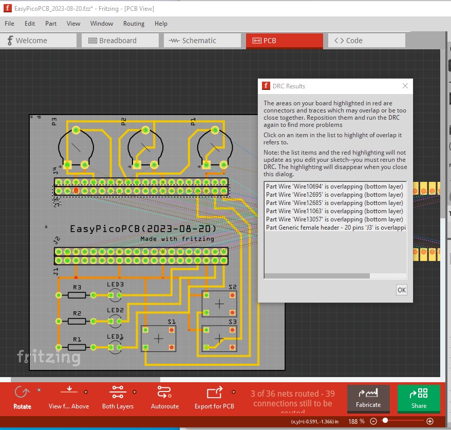
clicking on a line in the DRC report will highlight the connection in error with the overlap colored in red

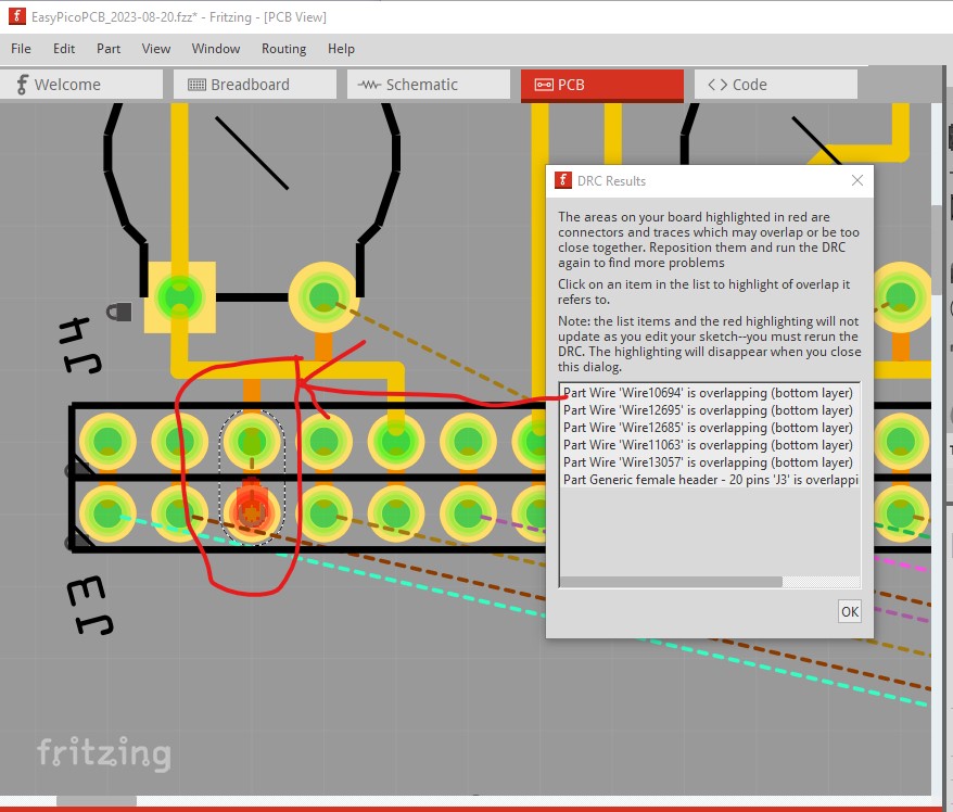
The rats nest line between the pins indicates there is no connection on the underlying trace. In addition there are a number of traces not routed on the pcb which perhaps need to be fixed for it to work.

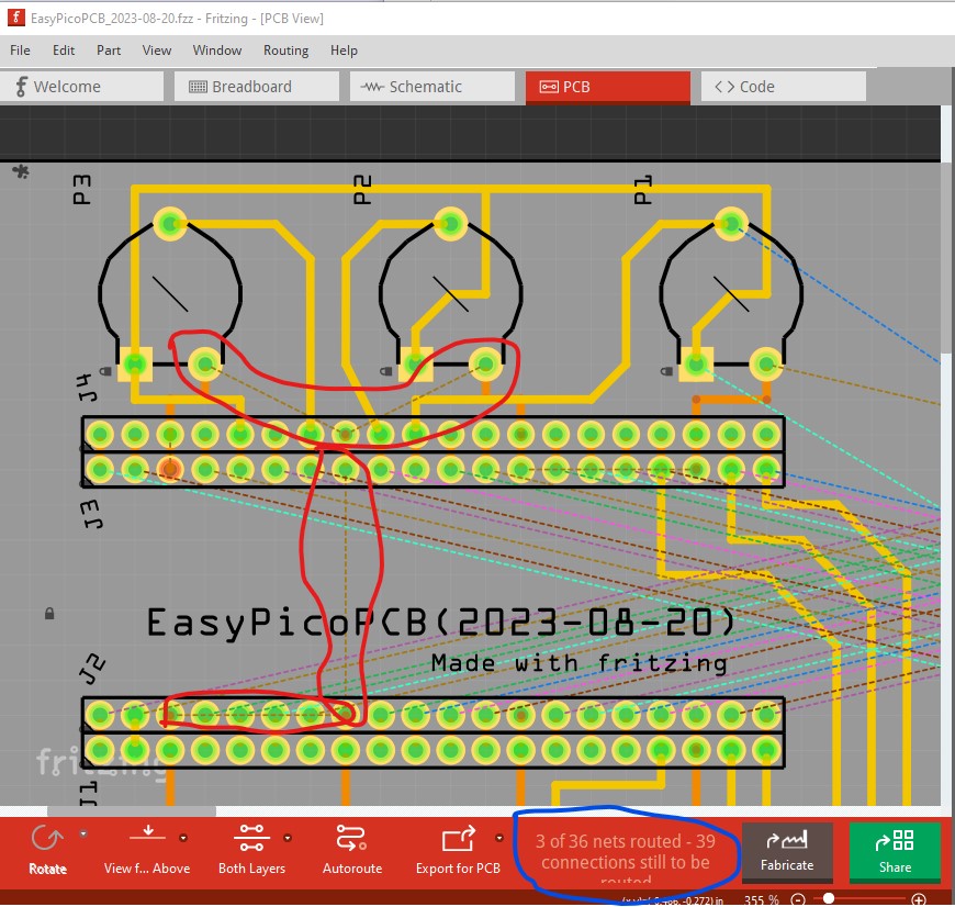
As well I believe the ground and power pins are connected internally on the board (I’m not sure of that as I don’t have a pico though!) and thus shouldn’t be connected on the pcb as that will potentially cause a ground loop which is undesirable. You would be best off to route all the rats nest lines to the cpu board to make sure that routing completes correctly and all connections go where you expect but that may get quite complex. A better solution is in the answer to this question:

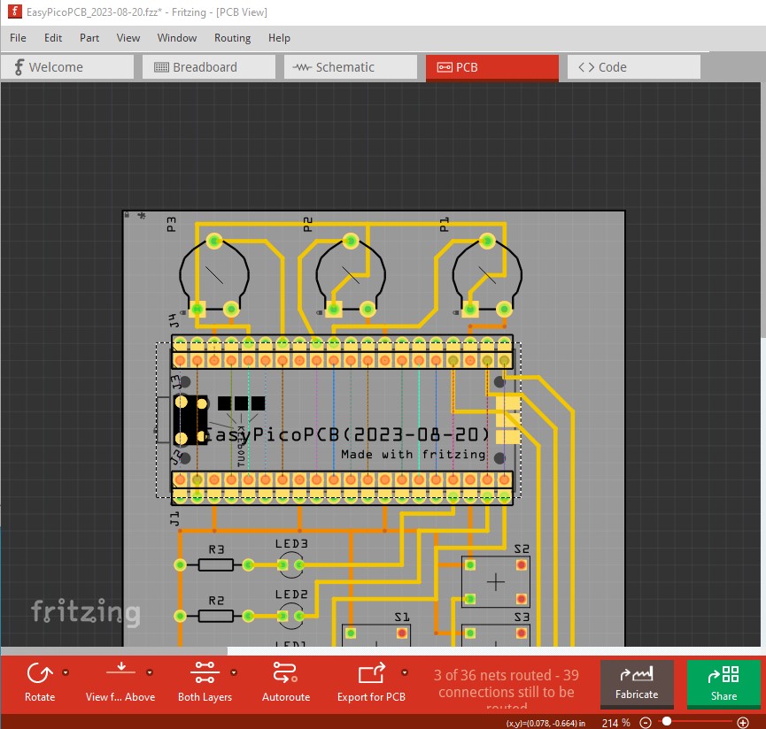
It isn’t clear to me exactly what you are trying to do here, I assume that you want the pico to plug in to the inner set of headers with the outer set being connect points on the pcb. If that is the case moving the Pico to the inner set like this should do what you want

You may also need to change to the fixed version of the pico available here (you appear to want the tht version rather than the SMD version.) The fix was offered to the RPI folks but I don’t know if they ever replaced the version on the RPI website with the fixed one.

I expect you will also have DRC errors with the pico in that position as the 2nd headers will overlap the pico part but that can be ignored as long as the gerbers look correct which they should.

Peter

Thank you Peter for your tips.

I simplified this project : I removed the Pico to have a clear view in the schematic and simpler PCB.

I checked the DRC fails : no error, good !

The ground pins are connected all together physically, normal (I checked with a multimeter).

About the - how to keep the “logic” (in breadboard, schematic) - I imagined than I can have the Pico on the breadboard, with its internal logic in the schematic (all connected) WITHOUT any physical wires/connections in the PCB. :innocent:

I will print the PCB into paper to check the scale of each component. I will also add some MicroPython code in this project.

My new project :
EasyPicoPCB_2023-08-22.fzz (91.7 KB)

Thanks again.
Mick

It now looks good. One thing that I would check with the pcb footprint is that there is enough clearance between the outside headers on the CPU and the CPU board. When the PICO is installed the edges of the board may block connections to the outside header if the width of the CPU board is too large. If that is the case moving the outside connectors up (for the top) and down for the bottom by 0.1in should provide sufficient room to connect wires.

Peter

Hello Peter,

you’re right ! I moved the external header of 3 mm.

EasyPicoPCB_2023-08-24.fzz (93.0 KB)

Here a picture of two Pico boards with different headers. Left one is a double header and the right one is 3.5 mm space between them.

Thank you :wink:

I forgot to add a code example… :innocent:

# EasyPicoPCB (2023-08-22)
# Raspberry Pi Pico : https://www.raspberrypi.com/products/raspberry-pi-pico/
# MicroPython : https://micropython.org
# Thonny IDE : https://thonny.org
import machine
import utime

# External button S1 (GPIO16, pin 21)
buttonS1 = machine.Pin(16, machine.Pin.IN, machine.Pin.PULL_DOWN)
# External button S2 (GPIO17, pin 22)
buttonS2 = machine.Pin(17, machine.Pin.IN, machine.Pin.PULL_DOWN)
# External button S3 (GPIO18, pin 24)
buttonS3 = machine.Pin(18, machine.Pin.IN, machine.Pin.PULL_DOWN)
# External LED LED1 (GPIO15, pin 20)
led1 = machine.Pin(15, machine.Pin.OUT)
# External LED LED2 (GPIO14, pin 19)
led2 = machine.Pin(14, machine.Pin.OUT)
# External LED LED3 (GPIO13, pin 17)
led3 = machine.Pin(13, machine.Pin.OUT)

while True:
    if buttonS1.value() == 1:
        print("Button S1 is ON")
        led1.value(1)
    if buttonS2.value() == 1:
        print("Button S2 is ON")
        led2.value(1)
    if buttonS3.value() == 1:
        print("Button S3 is ON")
        led3.value(1)
    utime.sleep(0.5)
    led1.value(0)
    led2.value(0)
    led3.value(0)
    utime.sleep(0.5)

Cheers.
Mick

Hi there !

Finally (after some changes) I create a Github repository for this tiny project :

Feel free to download, share, modify, create some issues… :wink:

Cheers,
Mick