UDOO NEO.fzpz (137.2 KB)
It´s been finished. It took a long time to understand how new parts are built up.
On this part some improvements may be nessesary. But it fulfills all my requirements and perhaps those of yours.
UDOO NEO.fzpz (137.2 KB)
It´s been finished. It took a long time to understand how new parts are built up.
On this part some improvements may be nessesary. But it fulfills all my requirements and perhaps those of yours.
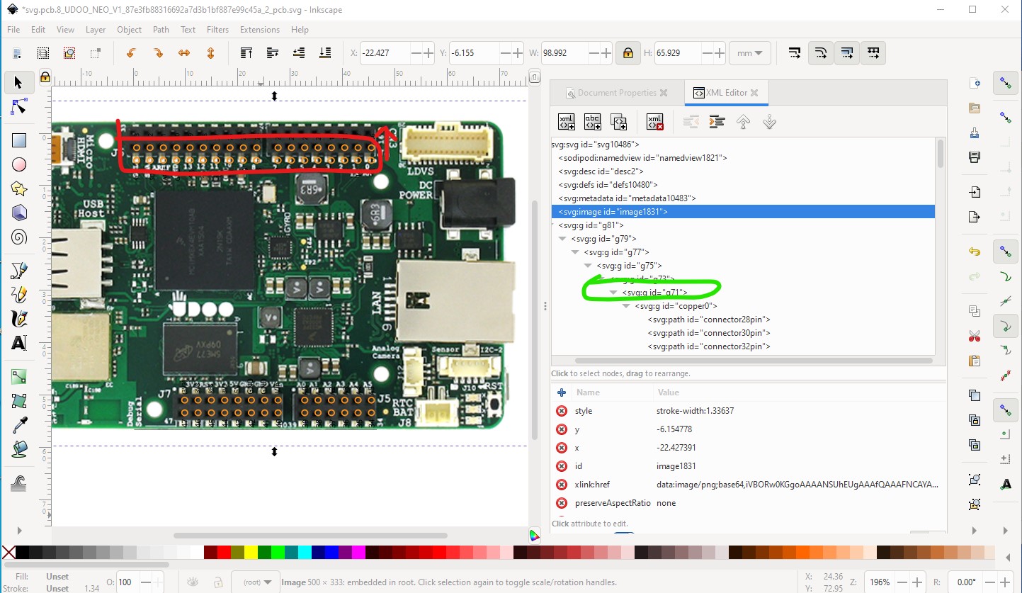
Your part has a few issues. It lacks a layerIds in breadboard and schematic and pcb appears to have the connectors on the top 0.1in too low. This is a jpg image of the board overlaid on the pcb svg image in Inkscape. Note the top row of pads is 0.1in too far down (breadboard is correct!) and it needs an id copper1 to replace g71 just above the copper0 group definition (circled in green in xml editor in the image) in order to generate holes in pcb. The holes should be 0.038in to take 0.1in headers but as the pads are non circular paths (and should be circles) no holes are in fact generated which is also a problem.
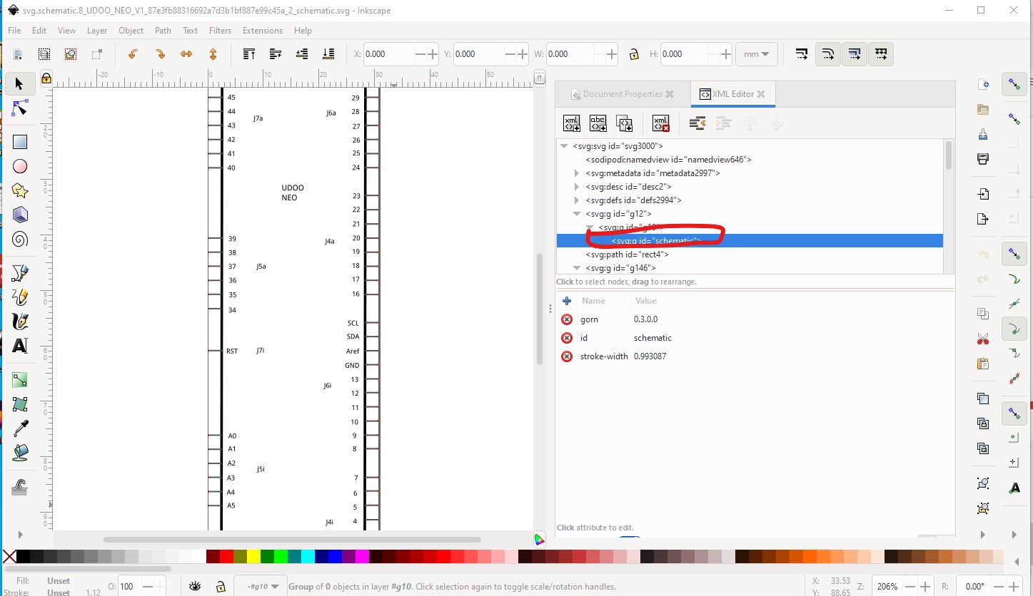
schematic has a layerId but it is empty
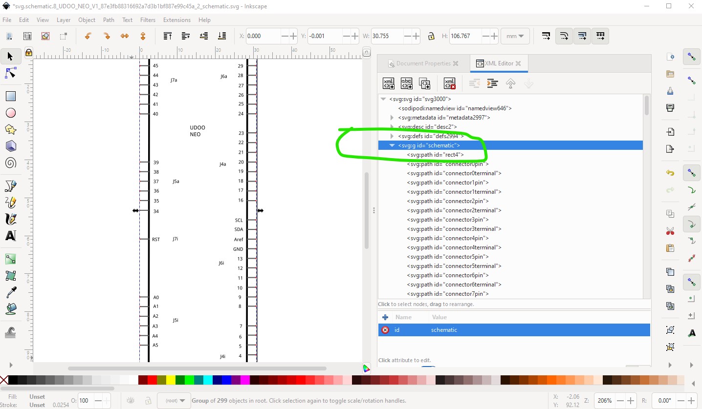
So in Inkscape I ungrouped everything then did Edit->select all then Object->group and set the layerId to schematic like this:
without correct layerIds the part will not export as an image from Fritzing. Same thing applies to breadboard, with the layerId being set to breadboard. If the part is doing what you need, there isn’t necessarily a reason to change it, but anyone else trying to use it needs to be aware of the issues noted above (especially if you are using pcb!)
Peter