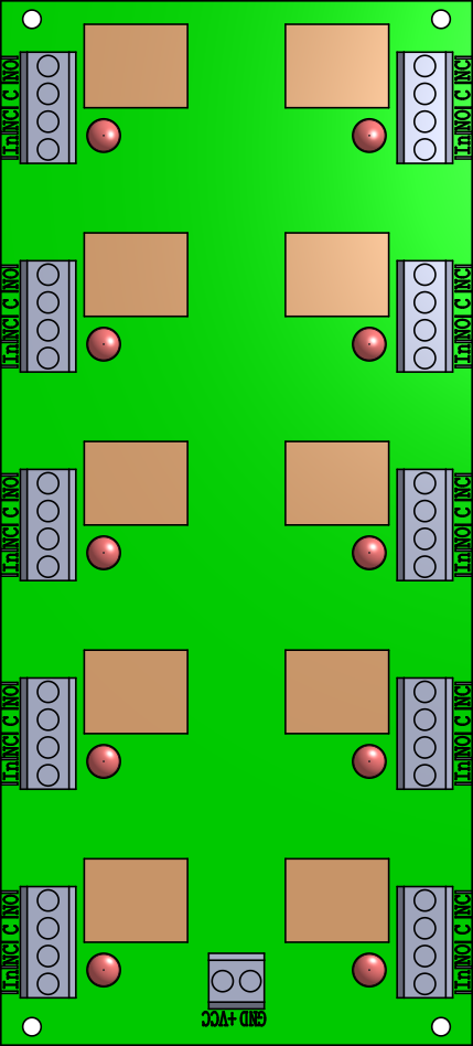
I’m currently trying to make a new part for a custom relay board I bought online. The board has 10 relays with 4 pins per relay (NO, NC, C, IN) + VCC and GND.
I exported an SVG file from the .step file for the part. In Inkscape I adjusted the SVG to match the page size with the drawing, and I grouped all objects together.
I start creating the part from a blank 42 pin IC. I then import the SVG to the part breadboard and assign all 42 pins. I save the part and give it a name. Once I use the part in my drawing, the breadboard image is only the black and white outline, and it loses all the color from the part. Checking the SVG file created by the part, it looks like it also gets saved as the outline without the color.
Upload the .fzpz file for the part and the breadboard svg with the colors in it (upload is th7th icon from the left in the reply menu) and one of us will have a look over it and see if we can tell you what is wrong.
Thanks Peter, I’ve attached all the documents and I also added the png of how the svg looks like in inkscape.
I’ll add the other files in a separate comment.
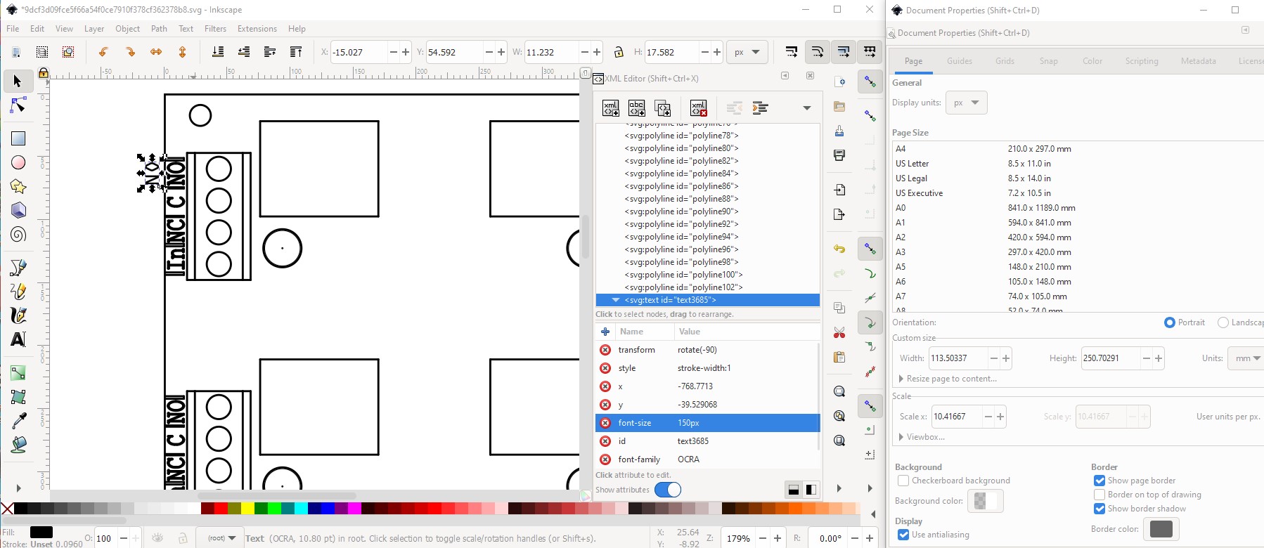
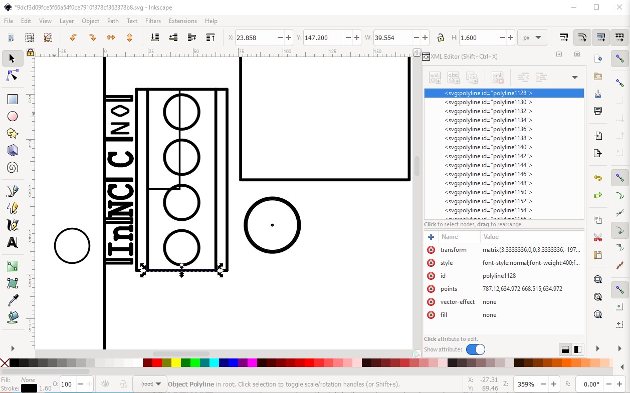
It looks like the conversion from step to svg is at fault. The svg has not translated the colors and has translated everything to polylines. I have only done a step conversion once, and I did the conversion manually from the step image like this (except here I started from your svg using Inkscape.) because I couldn’t find a way to convert from step to svg that preserves the colors (there may however be one that I don’t know about, I know almost nothing about step!)
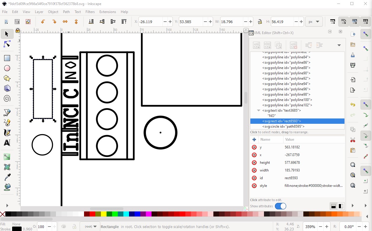
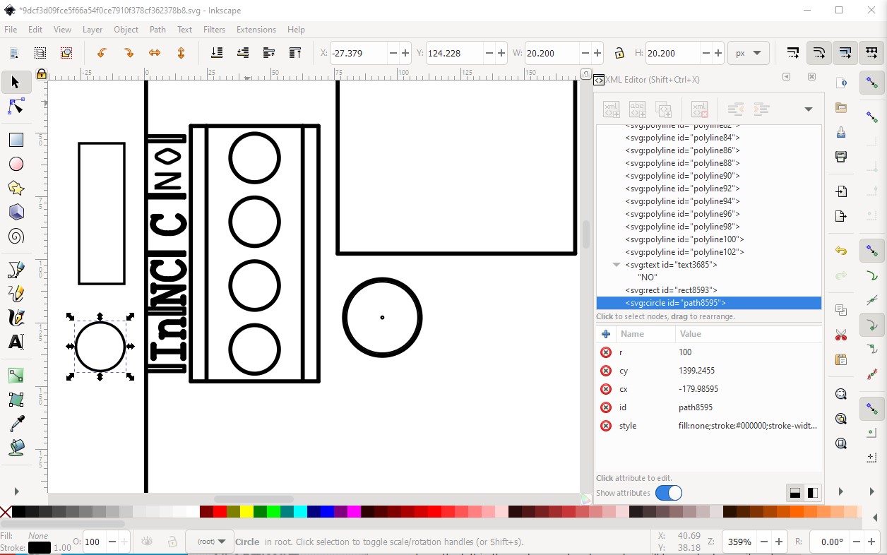
Then deleted the “no” created in polylines and moved the text in to its place. Then I created a rectangle (necessary to be able to set the fill color) and a circle to replace the rectangle and circles in the image.
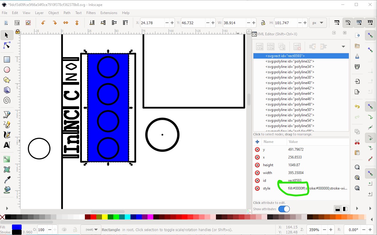
Then I moved the rectangle till the top left edge matches the rectangle made by the polylines then deleted the polylines in the rectangle (all 4 of them)
Now I can change the fill color of the rectangle to put the color back in the rectangle like this (I also needed to move the rectangle up in the svg drawing order so the circles still show in the fill)
here I used a fill of blue rather than the tan of the original, but you get the idea. Unfortunately you need to do this for all the elements in the step image unless you can find a way to get the conversion to an svg to do the translation for you. In this case I created one circle but didn’t move it in to the blue rectangle.
edit: Here is a copy of my changed svg for comparison
This is a great step by step. I suspected it might have had something to do with the .step to svg conversion but I was thrown off by the fact that the svg does show color at some point in the part creation, and then it doesn’t.
I’ll follow the same process you did and will fill the colors for all elements. I’ll upload the final part once it’s done.