On the Uno there is an internal connection from A4/A5 to SCL/SDA so in pcb it routes to the closest point (A4 / A5 in this case.) On the Arduino WiFi Rev 2 (which is what you are actually using) SCL/SDA does not connect to A4/A5 as it does on the Uno. So changing to the Arduino WiFi Rev 2 Fritzing part will keep pcb from trying to use A4/A5 as SCL/SDA. You can also manually route the SCL / SDA traces to the proper pins on the UNO in pcb.
I just looked at the Adafruit site which says the sensor can be powered either by 3.3V or 5V so what you want to do is change the Vin on the sensor from 3.3V to 5V like this:
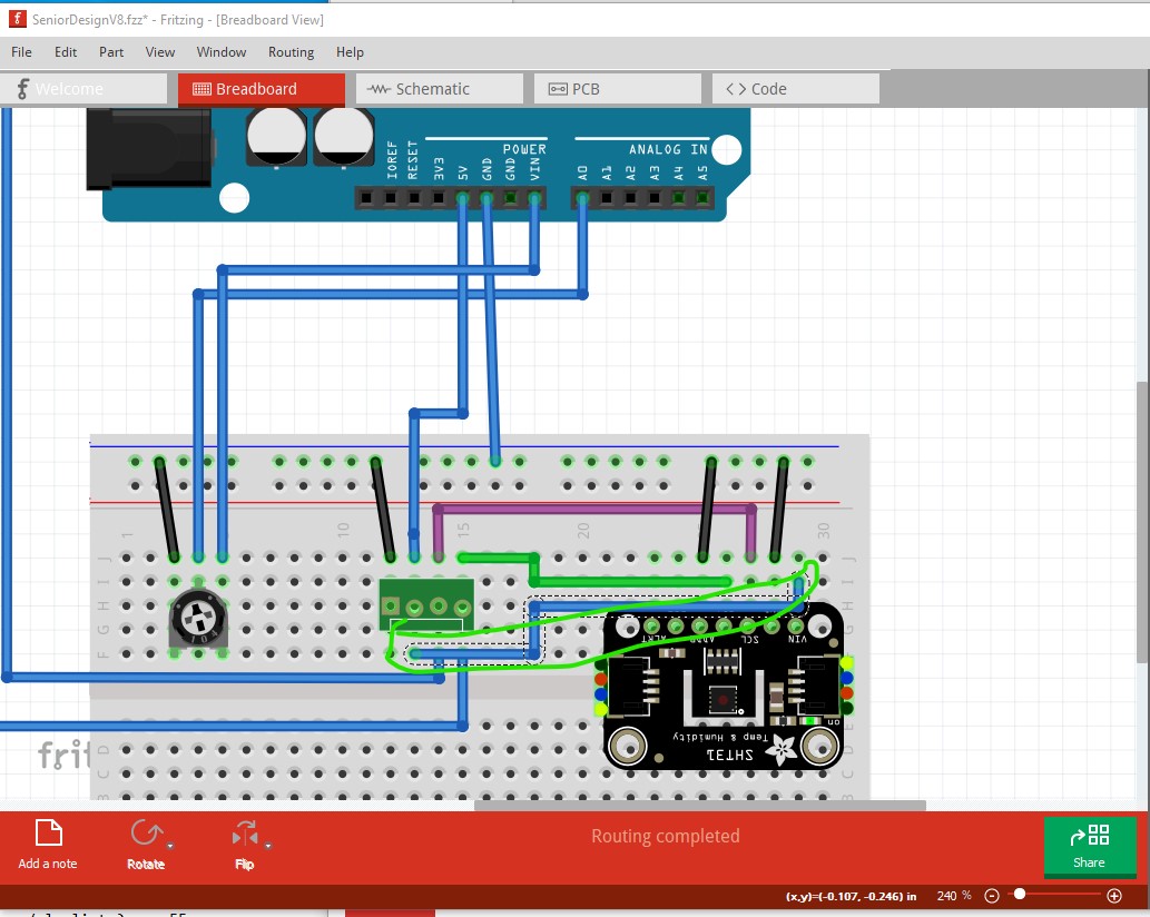
With the sensor running on 5V there is no need for level translation. In the original connection, the sensor is running at 3.3V but the I2C pins are being driven from the Arduino at 5V which can cause damage to the input pins on the sensor.
Assuming you want to measure the Vin voltage with the analog pin, you don’t need the pot but rather a fixed voltage divider. This circuit should do what you want.
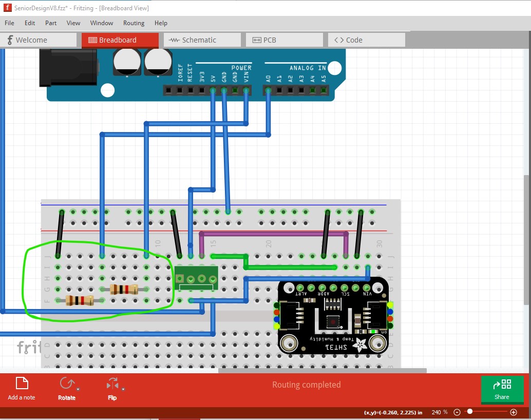
two 1K resistors replace the pot. They will divide Vin in half (so 9V in will produce about 4.5V at the analog input pin.) then you need to scale the value of the analog input value by multiplying it by a scale factor to change the measured value to volts to display. I think the analog input is 10bits which is 1024 steps so it should be somewhat close as is, but what may be easiest in this case is to change the pot to be about 250 ohms and put it in series with the top resistor like this:
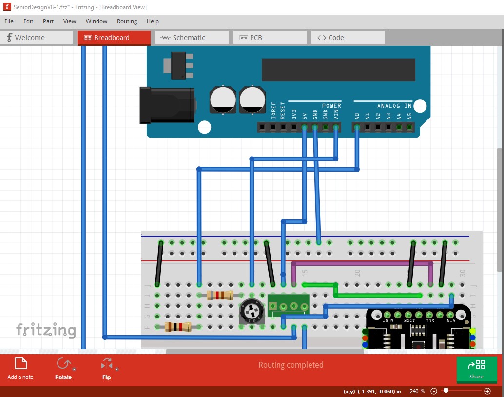
here I replaced the top 1K resistor with an 820 ohm resistor and a 250 ohm pot in series with it. Adjusting the pot will change the voltage at the junction of the resistors, so with 9V as Vin you should be able to adjust the pot so that the analog input reads 900 (equating to 9V) which is easier than calculating the scale value you need.
Peter