i tried to edit a part that i found in this forum wich was NC5FAV but i cant make it like it is in real life can someone help me/ explain how to achieved it correctly
From a quick look at the part file and product page, it looks to me like the existing part will work without any changes. What do you need to be different? Put NCSFAV in the part number field in inspector, and it should be ready to go.
when you look on manufacturer site on is straight out pin to pcb put the one i need have 90 degree angle so spacing between pin on pcb aren’t the same spacing see both link in pdf download
So you need a different pcb footprint. The information in the drawing pdf is enough to do that. Someone here might do that for you. It looks simple enough for someone that has done parts editing before.
The basic process, is to unpack the fzpz file (it is just a zip file), use an svg image editor (commonly Inkscape, but others work too) to move the connectors to where they are needed, and touch up the silkscreen boundaries. Then edit the fzp file to give it a new module id, change the text description, change tags and properties, to match the new part, then create a new fzpz from the result. Load that new part file and go.
I am going to guess you tried to edit the part with the Fritzing parts editor. It does not have any ability to change the graphic files. That needs to be done using an external program.
The Tutorials - Guides - How To’s - & Experiences forum category contains plenty of information (click the “all categories” drop down at the top of the forum page). Try the part creation series, and look for references to Inkscape and PCB. Plus maybe some references to editing the part definition meta data.
This should do what you want. As always print out the footprint at 1:1 and compare it to a real part before ordering boards. I didn’t change breadboard (so it is the original layout not right angle but will work the same.) As well I assumed that the “g” in the foot print is the shield and is therefore connected to the shield connection. You should check that is correct by using an ohm meter on a real part.
As to how I did this, I unzipped the original file that I made and changed the pcb svg to reflect the new foot print, which looks like this:
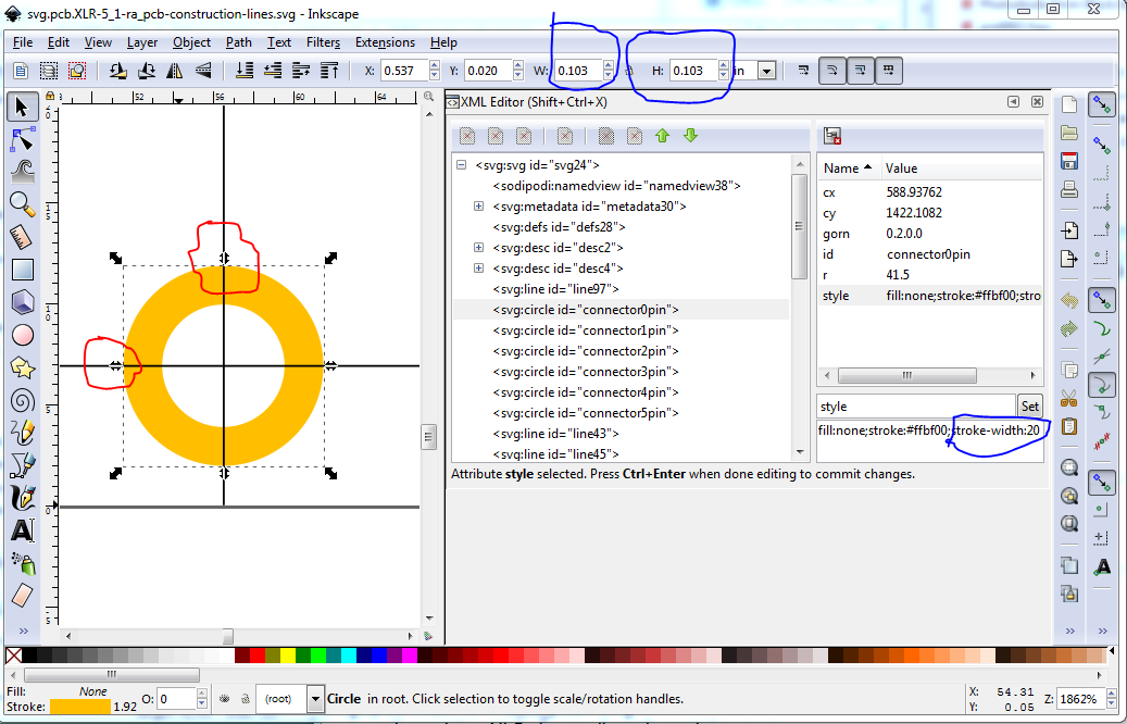
the construction line are from the measurements in the pdf footprint. The pads are set to the correct hole size (.047 and .063in as I recall) via the formula (in Inkscape) hole = dia * (2 * strokewidth). Then the pad was moved to intersect the construction lines like this:
The red circles are the pad being aligned and the blue circles are the pad size being set to 0.063in in this case (.103in diameter with a 20 thou stroke width.) After that I changed the moduleId and the family and the svg file names to unique new values in the .fzp file (you can compare the fzp from the original part to the one for this part to see the changes.)
You might want to try the new Inkscape 1.1 dev - 1.0 is a bit flaky -, because you can now type directly on the elements on XML editor, ie, you don’t need the set box at the bottom. 1.1dev stands alone in a folder, so shouldn’t install over your old INK, just unzip and run it from there.