Hello
New to the forum. New to the world of electronics. I’m trying get the electronics set up correctly for my fist project, a small fan to keep the solder fumes out of my face. I finally figured out how to wire up the LED switch so when pressed, the fan (also with LEDS) comes on with the LED switch also lighting up. However, I’ve blown the LEDs in two switches already once I adjust my power source past 3V/.5A to get the 12V fan working at a reasonable speed. I have a 1000 Kohm resister in the circuit but I don’t think I have the circuit set up correctly.
Can anyone help? Is there anything else I should be adding in the circuit other than the single resister?
Specs:
– 9VDC 650mA wall power source that will plug into the back of the fan box.
– 12v DC panel mount 2.1mm power jack
– 4-pin 16mm 12v DC pushbutton switch with LED (not the Adadafruit 5-pin metal ones - these are the plastic ones)
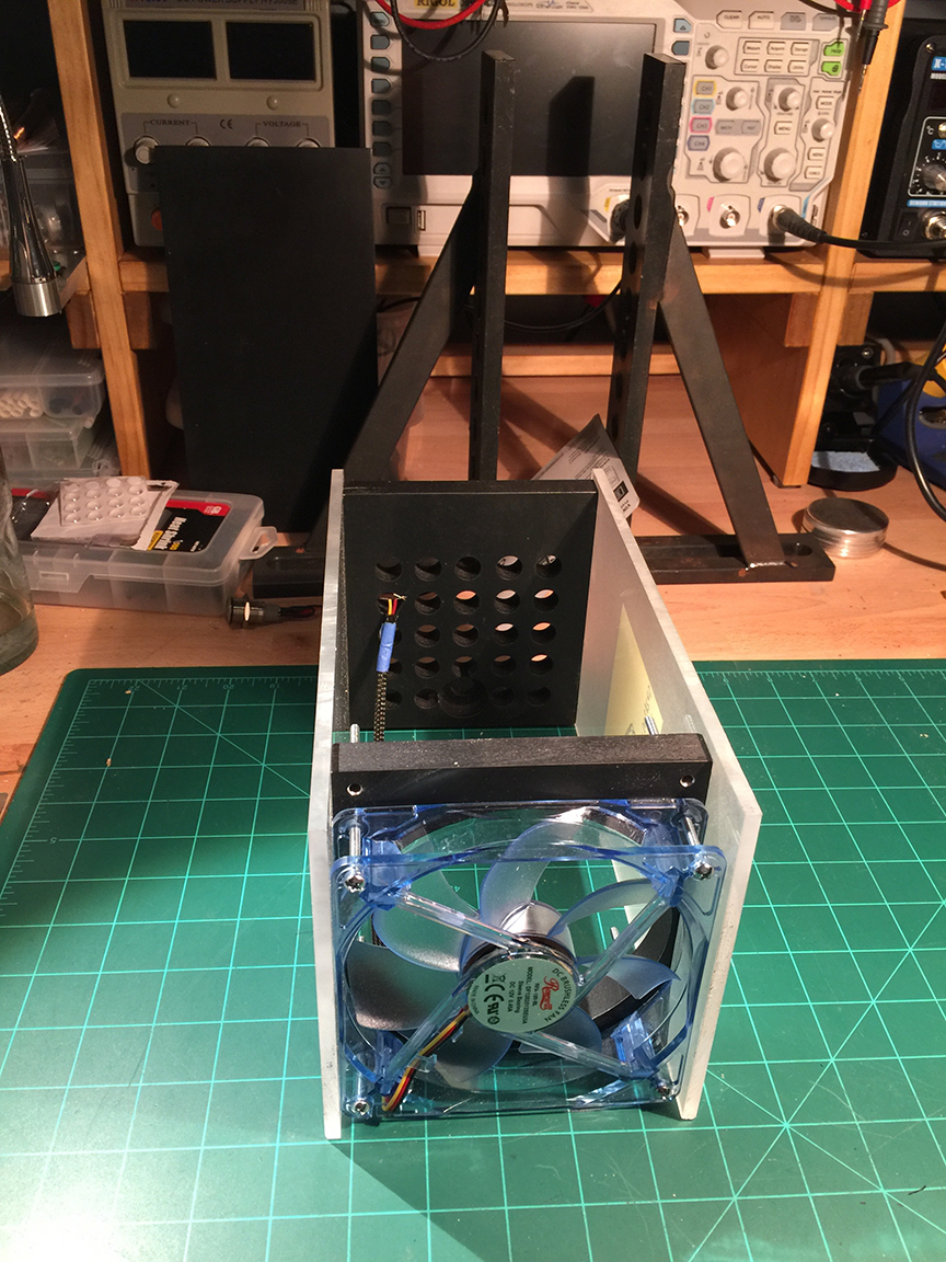
– 12V 120mm computer fan with 4 LEDS in each corner
Your sketch doesn’t appear to be correct although it probably explains the blown leds. The leds (assuming they are connected in parallel which sounds like the case if they run on 3v) want to see about 3v and 20 ma of current to operate. For that to be the case you need a resistor in the range of 500 ohms more or less (not 1 meg ohm as shown) so that with 9V at the top of the reistor about 6v is dropped across the resistor and 3v (more or less) is operating the leds. Ohms law tells us that I = E/R and thus the current with 6v across a 600 ohm resistor (to make the math simple) would allow 10 ma to flow in the circuit. As shown your circuit is applying the 9V directly across the LEDs which will draw way too much current and likely blow the leds. The switch (from the adafruit web site) appears to have a switch and two separate connections for the led. Your +9V wire needs to connect to one terminal of the switch and the fan and one end of a 470 ohm or so resistor. Then the switch either applies 9v to the fan and the fan and leds operate or it interrupts the 9V circuit and neither of them operate). The + (yellow lead in your drawing?) of the leds in the fan need to connect to the 470 ohm (or thereabouts) on the end not connected to the fan red power lead so that the resistor is in the way of the 9v and the leds. On the switch the ground of the led needs to connect to the black wires and the other end of the switch led to the same point on the resistor as the yellow wire. I’d suggest starting by getting the switch and the fan hooked up correctly (which may already be the case, if the switch can turn the fan off and on) and then go on to working on the leds.