Need help wiring Switches Arduino UNO

Hi all, great to see the Forum back online! Currently Im exploring Leon Battailles CAN-BUS Gaming on HackadayIO and I need some help wiring latching ON/OFF switches to an Arduino UNO Rev3.

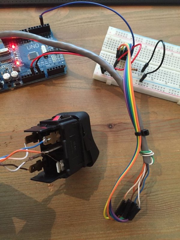
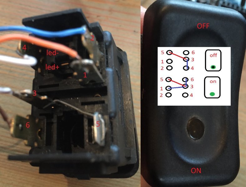
Im working on a real Truck Simulator and I want to use as much original Scania 144 parts as I possibly can. I measured all switches and they are pretty simple. Each of them is a latching switch with two positions (ON/OFF). ON has an LED that lit (24v) when its active. All switches have 6 PINs and two extra PINs for the LED. PIN 3 and PIN 5 are prewired by default.

What I need from you guys is two things:

1 What do these 6 pins do on a simple switch like this?

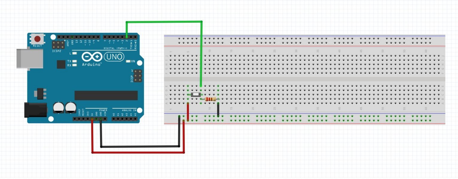
2 a Fritzing Project that helps me wiring 25 of these switches. I also need Arduino code + Debounce in it. I also want the Arduino board to check the switch-state upon start so I can tell the simulator in what positions the switches are so they can synchronize with the game (ETS2).

As a reward for helping I will put your name on the project contributors and together we can build something really cool!

Hope you guys want to help me get this beast gong!

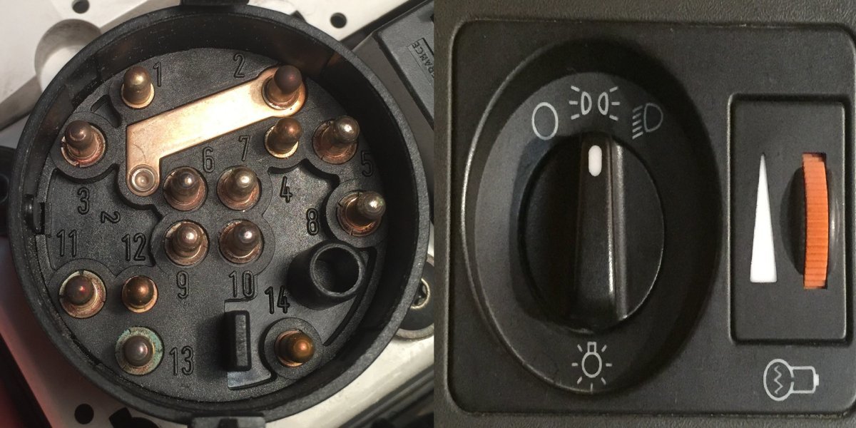
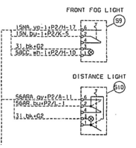
Light Switch ON/OFF Scania model 353626:

When OFF:
PIN 1 connected to: none
PIN 2 connected to: none
PIN 3 connected to: 3, 4, 5
PIN 4 connected to: 3, 4, 5
PIN 5 connected to: 3, 4, 5
PIN 6 connected to: none

When ON:
PIN 1 connected to: 1, 3, 5, 6
PIN 2 connected to: none
PIN 3 connected to: 1, 3, 5, 6
PIN 4 connected to: none
PIN 5 connected to: 1, 3, 5, 6
PIN 6 connected to: 1, 3, 5, 6

Light LED:
LED 1 – LED 2 = 80 ohm

Hi Jeroen, nice project, especially if you have the truck to go with it. :wink:
I only have the time to provide you with some pointers:

Debounce is definitely a good software strategy to apply here. On the hardware side, try experimenting with different values of resistors.

Get one button working properly, and then multiply. For reading 25 switches, you will need the Arduino MEGA, or alternatively a multiplexer IC if you want to stay with the UNO.

If you also need to switch buttons from the Arduino (output instead of input), this would be a classical application for solid-state relays. This separates the Arduino 5V from the 24V circuitry in the truck, and gives you more stability.

Btw, this kind of question would rather fit into the “projects” category of this forum, rather than “beginners”, as that is meant for beginner usage of fritzing.

Thanks for your help, I hope the Moderator can switch my topic, sorry for that.

Yes I will use relays to separate 24v and 5v, no worries there. I just need help geting a Friting Project with one Latching switch as an example. The second fase would be a Friting project with my 6PIN Switch and third would be a Fritzing Project with my 6PIN switch, LED and 24v side (Relay) and code for Arduino. With this Project I can start from there, build some experiance and move on to multiple switches connected and hopfully one day everything connected.

P.S. Yes I have the hardware :slight_smile:

Oooh, nice! I’m afraid I have no experience with the kind of switches you are using. I would do it the trial-and-error+googling-way. As soon as I’d have the circuit working on the breadboard, I’d recreate it in fritzing and then turn it into a PCB.

P.S. Moderator I am, so I just updated the category.

Haha ok sorry!

I have done this so far and it works! Problem is that my ON/OFF switch has now become a Toggle so ON=nothing ON/OFF/ON=ON?

I used this tutorial;
https://www.arduino.cc/en/Tutorial/Debounce

This is how I wired:

Maybe try this code first to understand what’s going on:
https://www.arduino.cc/en/Tutorial/StateChangeDetection?from=Tutorial.ButtonStateChange

Then adjust the logic, possibly including a debounce timer.

EDIT: Ok I tried to adjust the logic but it didnt help me. My toggle switch still acts like a pushbutton which I dont want. I need to know how to connect my 6-PIN switch as a 3-pin so I can use the Debounce methode in the picture below. If only I could know what all these pins do on my toggle switch?? It looks so simple but it isnt.

I will, this is what I have right now:

Found a diagram!

Good luck trying to make sense of it… :wink:

Oh I just did, its for the rotary lightswitch, not for a normal toggle switch:

When Light switch in stand 0:

PIN 1 connected to: none
PIN 2 connected to: 3, 6, 7
PIN 3 connected to: 2, 6, 7
PIN 4 connected to: none
PIN 5 connected to: none
PIN 6 connected to: 2, 3, 7
PIN 7 connected to: 2, 3, 6
PIN 8 connected to: none
PIN 9 connected to: 10, 13
PIN 10 connected to: 9, 13
PIN 11 connected to: none
PIN 12 connected to: none
PIN 13 connected to: 9, 10
PIN 14 connected to: none

When Light switch in stand city:

PIN 1 connected to: 1, 6, 7
PIN 2 connected to: none
PIN 3 connected to: none
PIN 4 connected to: 4, 8
PIN 5 connected to: none
PIN 6 connected to: 1, 6, 7
PIN 7 connected to: 1, 6, 7
PIN 8 connected to: 4, 8
PIN 9 connected to: 9, 10, 14
PIN 10 connected to: 9, 10 ,14
PIN 11 connected to: none
PIN 12 connected to: none
PIN 13 connected to: none
PIN 14 connected to: 9, 10, 14

When Light switch in stand Dim:

PIN 1 connected to: 1, 6, 7
PIN 2 connected to: none
PIN 3 connected to: none
PIN 4 connected to: 4, 5
PIN 5 connected to: 4, 5
PIN 6 connected to: 1, 6, 7
PIN 7 connected to: 1, 6, 7
PIN 8 connected to: none
PIN 9 connected to: 9, 10, 14
PIN 10 connected to: 9, 10, 14
PIN 11 connected to: 11, 12
PIN 12 connected to: 11, 12
PIN 13 connected to: none
PIN 14 connected to: 9, 10, 14

This should be it:

OK we nailed it! PIN1 and PIN3 are the LED 24v and PIN2 is always the P-contact. All switches are different but they can be modified by removing the cap and change PINs with a little tool.

This topic can be closed, I will start a new one for this project with different questions about programing Arduino and Wiring.

Congratulations! If you happen to have a simple circuit for it, would be great to post a screenshot here for other’s reference. Thanks :slight_smile: