Need Help Troubleshooting a Circuit

Hello, everybody.
I’m a mechanical engineering student and a beginner in the world of electronics and I need some help with my project.
The project consists of an automated cistern that will have two water sensors and a water pump.
I’m trying to connect a diode and a transistor to my relay, but I don’t know if I’m doing it correctly. I’ve tried to make a schematic of the whole project, but I don’t know if the wiring and components are correct.
Attached is an image of the circuit and the schematic.

NOTE: This is my first time using the forum. If I post this topic in the wrong place, let me know and next time I’ll do it correctly :slight_smile:

1 Like

You need to upload the sketch this was made from (the .fzz file, upload is 7th icon from the left in the reply menu.) Pictures are pretty much useless in diagnosing problems.

Peter

Hello, Peter

I attach the sketch as you requested.

Esquema automacao cisterna.fzz (52.3 KB)

As far as I can see (unless I am missing something) the transistor doesn’t do anything. The relay module appears to have a transistor driver in it and will operate directly from the Arduino pin.

All the circuitry circled in red should be able to be able to be deleted without any problems as far as I can see. There appears to be a transistor driver circuit included in the relay module.

If you provide 5V from the Arduino to the relay module everything circled in red can be deleted like this

edit:

Other than I deleted the ground wire when I should not have, it should look like this

As well the level sensors need to be connected to the Arduino presumably to shut the pump on or off depending on the water level, I assume one is for low water lever (pump on) and the other for high water level (pump off.)

Peter

1 Like

Thank you very much, Peter! I didn’t know that the relay module had an integrated diode and transistor.

One more question: do you know if the relay module for Arduino, like the one I’m attaching in the image for reference, has the diode and transistor integrated?
image

Yes it looks like it. The SOT23 package circled in green looks to be a transistor driving the relay. They are fairly common on the relay boards so as to work with Arduinos.

capture

Peter

1 Like

Okay. Thanks again for all your help :smiley:

If you have more questions don’t hesitate to ask. The only stupid question is the one you don’t ask because you think it is stupid …

Peter

1 Like

Looking at the sensors, I have a question. Is it mandatory to use a resistor to connect them to the Arduino?
I’m using these sensors, image attached.
image

I found a datasheet for the same type of sensor I’m using, but it’s from a different manufacturer and the one I’m using doesn’t mention the manufacturer.

I assume the sensor is two wires which acts as a switch, so one wire goes to ground, and the other to an Arduino input port. It doesn’t need a resistor, but you need to enable the builtin pullup resistor on the Arduino input port (or pull the port up with an external resistor to 5V so when the switch is open the pin is pulled up to 5V, but the internal pullup is more convenient since it is already in the Arduino so less wiring!) A low level is less than 0.7V and a high level is > 2.4V but an open switch without a pull up resistor may let the voltage be in the 0.7 to 2.4V range and cause a problem as the input value is indeterminate and may read as either high or low. The pullup (either internal or external) makes sure it is above the high threshold and is thus a high level.

Peter

1 Like

Yes this is what Peter meant

void setup() {
    pinMode(10, INPUT_PULLUP);
}

With external circuit

void setup() {
    pinMode(10, INPUT);
}

And the final setup

const int button = 10;

const int ledG = 9;
const int ledY = 8;
const int ledR = 7;
const int ledB = 6;

const int relay = 5;

void setup() {
  pinMode(button, INPUT_PULLUP);

  pinMode(ledG, OUTPUT);
  pinMode(ledY, OUTPUT);
  pinMode(ledR, OUTPUT);
  pinMode(ledB, OUTPUT);

  pinMode(relay, OUTPUT);
}

void loop() {
  if (digitalRead(button) == 0) { // Closed switch
    // code here
  }

  if (digitalRead(button) == 1) { // Open switch
    // code here
  }
}


1 Like

Guys,
thank you very much for your help with the project. I had seen the messages, I tested it and it worked in my project, but I forgot to reply.

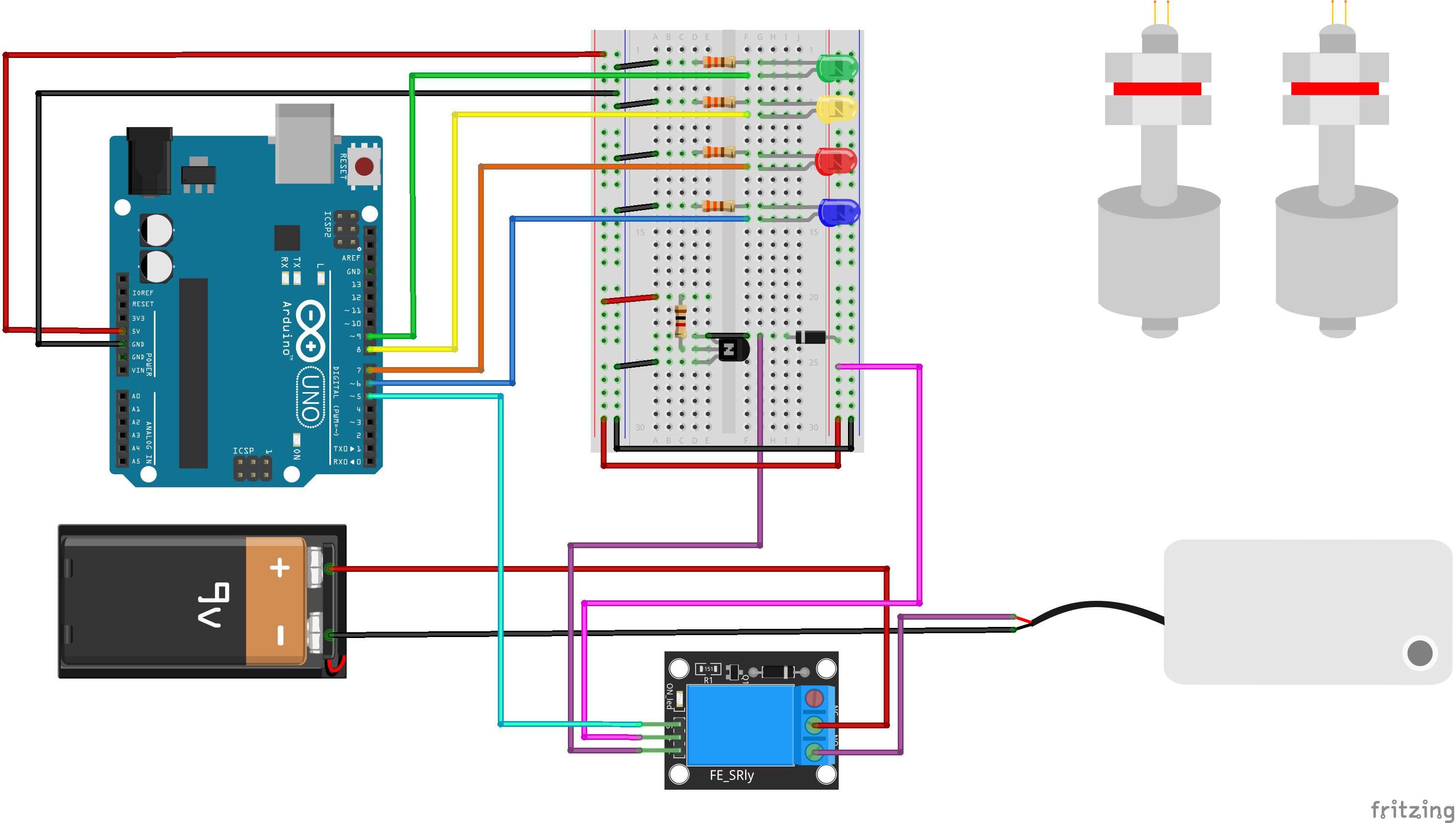
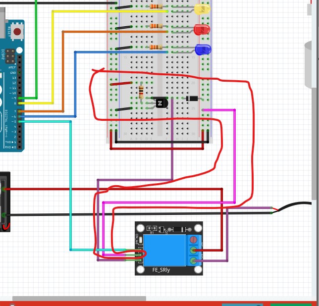
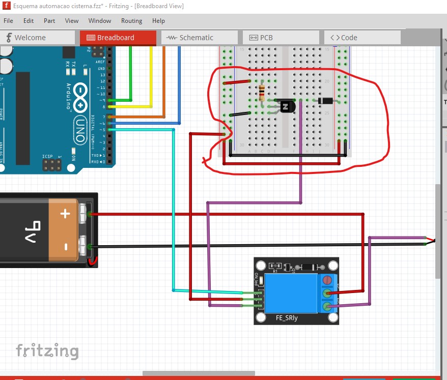
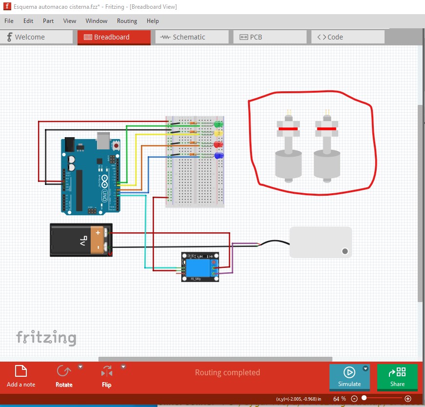
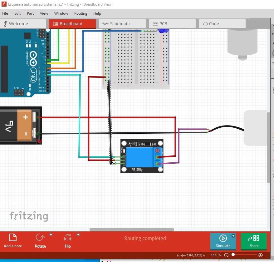
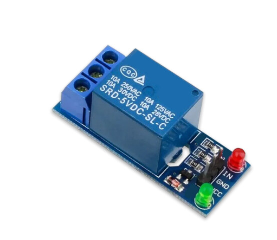
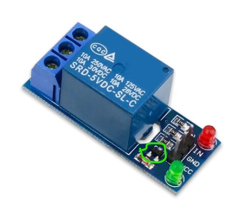
However, now I have a problem where my relay doesn’t want to activate the water pump with all the components inserted in the circuit…I’m using an external 12V and 3A supply to power the Arduino Uno R3, thinking it’s a power supply problem, but it still didn’t work. I don’t know if it’s something in the circuit or something to do with the code. I’ll insert the code here for you to analyze and if you can help me with this problem.

I’m from Brazil and some of the comments I made in the line of code were to remind me of what each line does.

I

Code:

int ledB = 10;
int ledR = 9;
int ledY = 8;
int ledG = 7;
int bombaH2O = 6;
const int sensor01 = 5;
const int sensor02 = 4;
//Definição de todas as entradas.

bool nivelMaximoDetectado = false; //Detecta se o nível está no máximo.
unsigned long tempoNivelMaximo; //Armazena tempo em que o nível máximo foi detectado.
const long atrasoLigamento = 2000; //Tempo para o qual deve acionar o led azul e a bomba, após o evento de detecção.
bool bombaLigada = false;

void setup() {
pinMode(ledB, OUTPUT);
pinMode(ledR, OUTPUT);
pinMode(ledY, OUTPUT);
pinMode(ledG, OUTPUT);
pinMode(sensor01, INPUT);
pinMode(sensor02, INPUT);
digitalWrite(bombaH2O, LOW);
digitalWrite(ledB, LOW);
digitalWrite(ledR, LOW);
digitalWrite(ledY, LOW);
digitalWrite(ledG, LOW);
Serial.begin(9600);
Serial.println(“Iniciando controle cisterna…”);
//Definição qual a função das entradas.

}
void loop() {
int nivelsensor01 = digitalRead(sensor01);
int nivelsensor02 = digitalRead(sensor02);

if ((nivelsensor01 == LOW) && (nivelsensor02 == LOW)){
digitalWrite(bombaH2O, LOW);
digitalWrite(ledB, LOW);
digitalWrite(ledR, LOW);
digitalWrite(ledY, LOW);
digitalWrite(ledG, HIGH);
Serial.println(“Cisterna sem água.”);
nivelMaximoDetectado = false;
bombaLigada = false; //Desliga a bomba e reseta o estado, ou seja, verifica se é verdade, se não continua o código para atender aos outros requisitos.

}else if ((nivelsensor01 == HIGH) && (nivelsensor02 == LOW)){
digitalWrite(bombaH2O, LOW);
digitalWrite(ledB, LOW);
digitalWrite(ledR, LOW);
digitalWrite(ledY, HIGH);
digitalWrite(ledG, LOW);
Serial.println(“Detectado agua na cisterna”);
nivelMaximoDetectado = false;
bombaLigada = false; //Desliga a bomba e reseta o estado, ou seja, verifica se é verdade, se não continua o código para atender aos outros requisitos.

} else if ((nivelsensor01 == HIGH) && (nivelsensor02 == HIGH)){
//Nível máximo detectado.
if (!nivelMaximoDetectado){
//Se o nível máximo for detectado, então deve executar estas condições do “if”.
digitalWrite(ledR, HIGH);
digitalWrite(ledY,LOW);
Serial.println(“Cisterna nível máximo. Iniciando medidas de drenagem”);
tempoNivelMaximo = millis(); //Armazena o tempo exato em que condição de nível máximo é armazenada.
nivelMaximoDetectado = true; //Detecta a condição de positivo para condição de HIGH-HIGH dos sensores.
} else {
if (millis() - tempoNivelMaximo >= atrasoLigamento){ //Essa equeção define se o tempo para o atraso de ligamento do led azul e da bomba é atendidada (maior ou igual a 2s).
digitalWrite(bombaH2O, HIGH);
digitalWrite(ledB, HIGH);
digitalWrite(ledY, LOW);
digitalWrite(ledG, LOW);
Serial.println(“Bomba acionanda. Drenando agua.”);
bombaLigada = true; //Marca que a bomba foi ligada.
}
}
}
else if (bombaLigada && (nivelsensor01 == LOW) && (nivelsensor02 == LOW)) {
//Se os sensores abaixarem para o nível de LOW, então a bomba cessa seu funcionamento.
digitalWrite(bombaH2O, LOW);
digitalWrite(ledB, LOW);
digitalWrite(ledR, LOW);
bombaLigada = false; //Bomba desligada.
nivelMaximoDetectado = false; //Com os dois sensores no LOW, então essa condição não se torna verdadeira.
}

delay(2000);

}

The place to start trouble shooting is the relay board. To do that unplug the signal wire to the relay board from the Arduino, then connect the signal wire to ground and then 5V and see if the pump starts in either position. If the pump doesn’t start, there is something wrong in the relay board. If the relay board works then there is something wrong with your software, so first connect the relay back to the Arduino pin and use a test program to set the port off and on and make sure the Arduino can cause the relay to turn the pump on and off. Then check the rest of your code for errors.

Peter

1 Like

By running a few tests and modifying a few lines of code, the circuit worked as it should.

Thanks again for your help! :smiley: