I started to create the shape of the PCB and I don’t know how to continue from there to create the layers of the board I want the board to have 2 layers if you can help me I would be happy

Thanks for the helpers
I started to create the shape of the PCB and I don’t know how to continue from there to create the layers of the board I want the board to have 2 layers if you can help me I would be happy
Thanks for the helpers
Your outline has some issues. It is dimensioned in px (I changed that to inches, which means it is likely now the wrong size and needs to be rescaled!) and the format was incorrect. In addition it appears that it will create two boards unconnected to each other which is likely not what you want. This is the corrected (but probably missized) svg:

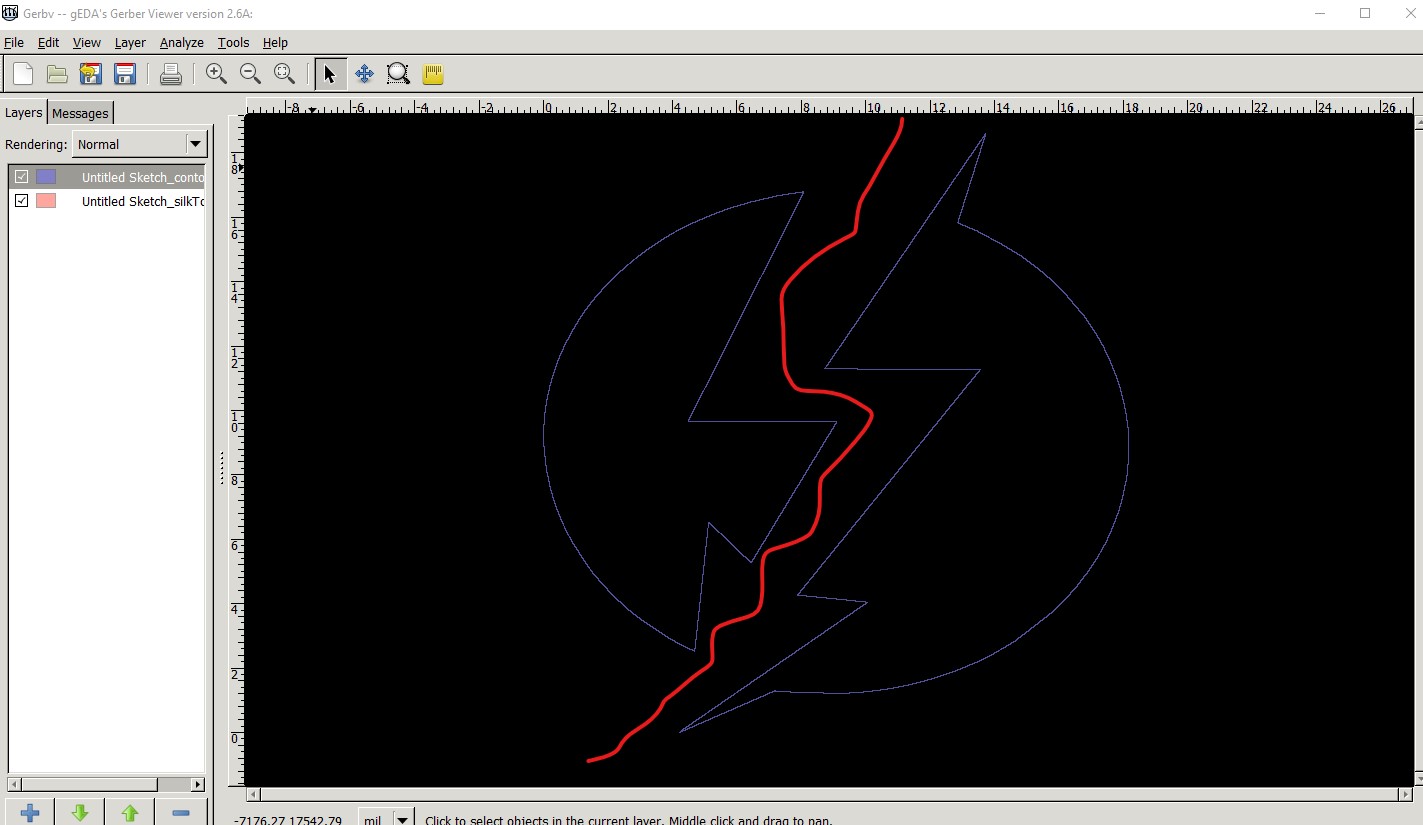
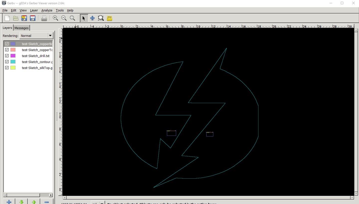
and here is the gerber output that it produces (which is likely unusable!)
I think the mill will give you two unconnected boards at the red line which I expect is not what you want. Are you trying to make a logo rather than a board outline perhaps? Is the svg intended to be on silkscreen rather than the board outline?
Peter
Thanks peter, yes it’s 2 PCBs not connected I wanted the total size of the two boards to be 470mm X 470mm so that’s why I uploaded the picture complete and not divided
can you fix it?
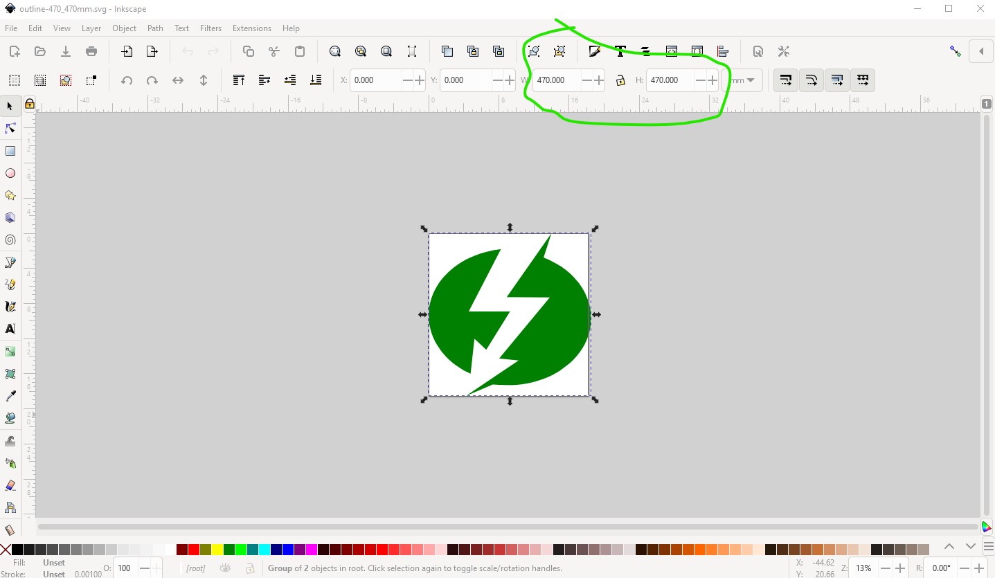
Yes, this svg should be 470mm by 470mm.

I think making a sketch like this should do you:
test-Sketch.fzz (5.8 KB)
For reasons I don’t understand (but probably to do with the paths) the image is slightly lopsided. While the svg is 470mm by 470mm
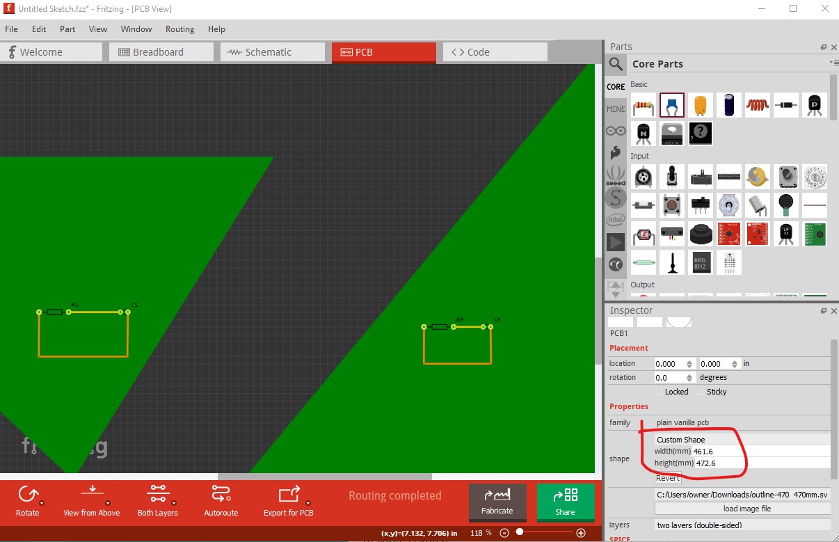
when loaded in to Fritzing is is slightly shorter in one dimension and slightly longer in the other
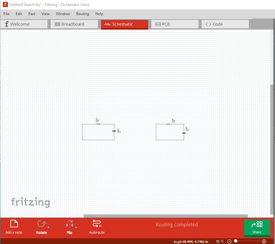
(circled in red in Inspector on the lower right.) Changing the dimensions only scales the other value. If you set components on the boards as I have done here, you will need to separate them in schematic like this, but it should work fine.
which looks like this in the gerbers. I’m not sure what the board house will make of this though! The milling in to two boards may cause issues, you will have to see what they say about it I expect.
Peter