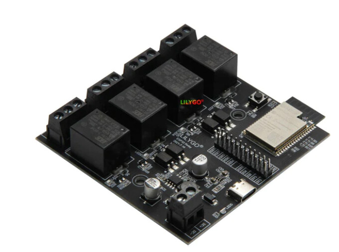
I have found many TTGO in the parts forum, but no luck finding the one I need. I’m looking to explain a friend that isn’t very initiated into electronics how to connect it. Could somebody help me?
I can’t find any good datasheet, but this website has all the needed info (it only works on chromium based browsers)
You presumably have a Fritzing version prior to 0.9.10 (and the current version is 1.0.1) since (AFAIK) the link is intended to provide a year of updates. That said it is well worth upgrading to 1.0.1 as a bug that causes routing database corruption has been at least mostly fixed in 1.0.1 and that alone is worth upgrading for. The usual solution for database corruption is start a new sketch from scratch which may become corrupted again. 1.0.1 is likely a much better all around solution.
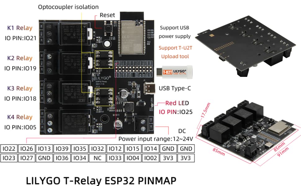
If I knew where any of those were they could be added. The board was made from this jpeg image
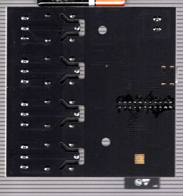
the two mounting holes are there in breadboard and on the silkscreen in pcb (you would need to drag a hole in to pcb in the sketch to actually drill a hole assuming you are making boards.) The position of the relay pins is a mystery as they are on the bottom of the board and presumably can’t be soldered to. Same with the position of the screw terminal pins. If you have a board and can measure the x/y position of the holes they can be added easily enough. I would think you would be better off to just mount the board and use the existing screw terminals and relays (to do anything else you would need to unsolder them which is likely to destroy the board1) unless I am not understanding what you mean.
I assume you want pads in pcb with the intent of unsoldering the relays and screw terminals? That is possible (although of limited use!)
edit:
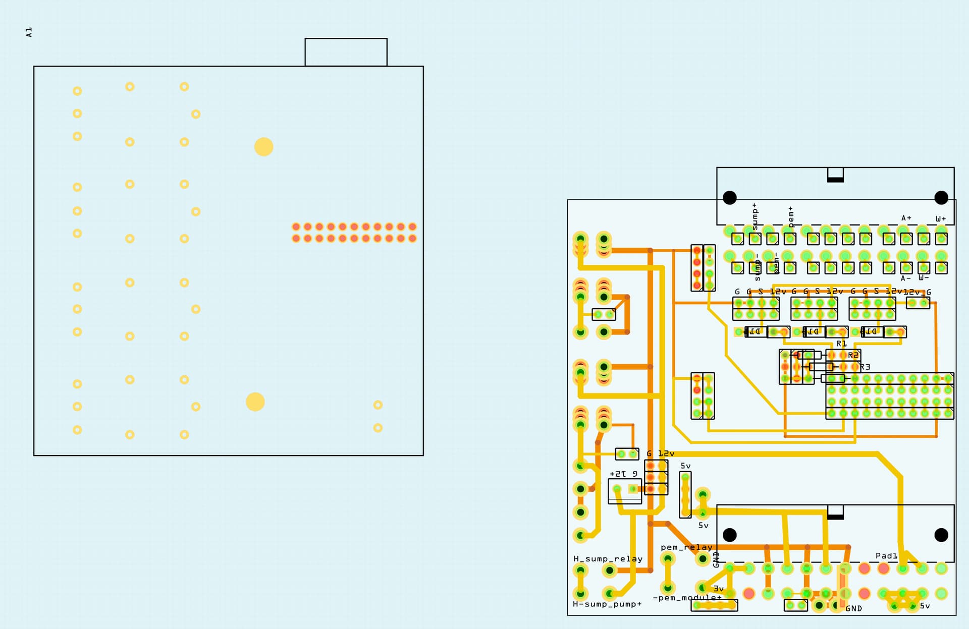
OK this part may do what you want. The added holes are only pads in pcb (not connections!) and the two mounting holes are drilled. The added holes are sized at 0.038in which will take a 0.1in header but may not be big enough for either the relay pins or the screw terminal pins. They may also not be in the right place depending on how good the jpg image is.
I’m designing a daughter board which turns the Lilygo relay board into an aquarium pump controller and allows for connecting various sensors, probably even w5500 ethernet if time permits.
I don’t think I’ll be doing much relay desoldering but having this part available will certainly make the whole process easier. TYTYTY.