I am using a ili9341 8 bit parallel with esp32.
Using mcukvb Library to make this thing work.
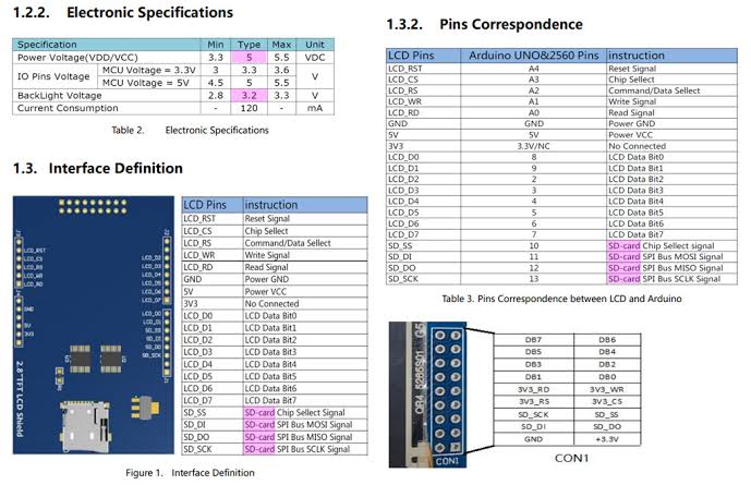
In the picture above , it is shown a double row header point of ili9341 named “con1”.
Esp32 runs smoothly by mcukvb if i connect the pins of esp32 to Arduino module pins of tft. But if I connect my wires to the con1 header ,the lcd does not work. seeking help to solve this issue…it would be much better if i can connect my wires to the con1 header rather than connecting to the arduino shaped moduler header.
It doesn’t look like you can entirely. The db lines (0-7) appear on con1, but the lcd signals lcd_rst to lcd_rd do not, so you would need to connect at least those to the Arduino pads. You would need to check with an ohmmeter that db0-db7 on con1 in fact connect to LCD_D0 to LCD_D7 on the arduino connector, if they don’t (and the names on con1 make me think they are a different data bus) then the arduino connector looks to be your only choice.
There is a user, david_prentice, that frequents that area often and is very knowledgeable when it comes to displays. You mentioned the mcukvb library. When I google for that, I get results for the mcufriend_kvb library and he’s the guy who wrote that library. If you post there, include a wiring diagram and a link to a data sheet or information about the display.
I’m thinking you have all the connections you need on the “con1” connector that you will need to run the display. I’m curious as to why you want to run in 8 bit mode. Using SPI, and fewer connections, on an ESP32 with a 2.8 display like this works really well, really well.
I disassemble the lcd…
I have discovered that there is 2 chip named 74LVC245 . Downloaded it’s datasheet seems like it is octal bus transceiver. The inputs (uno shield pins) all reached to A0-A7 and output I receive from B0-B7. Those output reached in the lcd’s flexible pcb. After seeking the voltage I found out all the input signals is converted to 3.3 volt in 74LVc245 output (B0-B7). Con1 connection correspondences all the 3.3v output of 74LVC245. I thought direct 3.3v output of esp32 will work fine… The led flickers a little but the screen remains white. Mainly somehow I am not getting the function of octal bus transceiver from the datasheet and I have no experience with this genere of chips. I am guessing this chip is working as level shifter.
Hi man,
At first thanks for your answer & specially for the arduino forum for LCD .
Yah I know david is the author of mcukvb Library.I have posted issues in his GitHub library time to time. But this time I think this is not the issue with his library.
This is the issue of 74LVc245 chip nothing else . Just trying to understand what is the function of this chip here. I never worked with octal bus transceiver.I am guessing this chip is working as level shifter.
Right now, SPI version is not available in my local market & I don’t have enough time to wait for SPI to reach from alibaba or Banggood for some reason.
The circuit board I designing should be small . So problem is i was looking for short solution of using Con 1 instead of using arduino shield pins.
and a level translator, the input voltage is specified at 5.5V even with 3.3V Vcc (which is unusual in bus transceivers ) so you are correct it is at least partly level translating. It also has an output enable, so if the second 74LVC245 is what connects the con1 data pins to the data bus, unless its output enable is low (and the other 74LVC245’s oe is high!) the data won’t get through to the data bus which may be your problem here. Pin 19 is the output enable so you may need to figure out what is driving it and arrange for pin 19 on the chip connected to con1 to be low which may get the data where it needs to go.
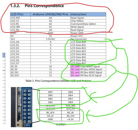
However the problem I originally saw is that the parallel drive signals (circled in red above) don’t appear on con1. If you can run wires from your board to the connections on the LCD that should work (assuming you can get the con1 data lines to enable.) But it looks to me that your only choice is running wires from the Arduino pads on the LCD to your board for the control lines and thus the data bus shouldn’t be much more of a problem. You need the control signals to tell the lcd controller what to do with the data on the data bus (and to drive the data bus in the correct direction!) It is possible that they don’t intend for the LCD data lines to be driven from con1 and thus it isn’t possible to use con1 to drive the LCD, but I don’t know for sure. These devices are rarely well enough documented to be sure of much of anything . Hope this helps.
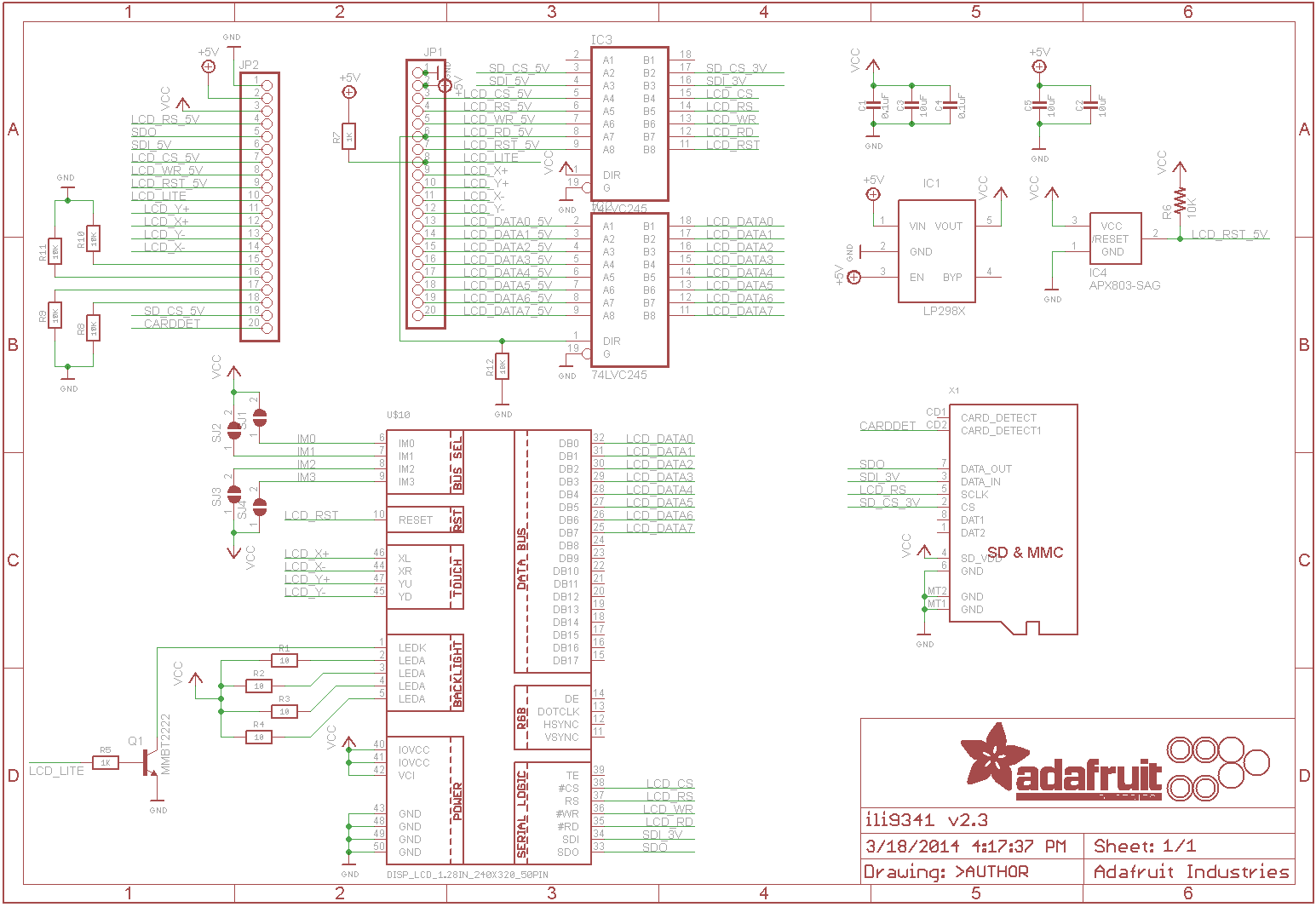
I found this schemetic.
After analyzing this I see only LCD_rst pin is not available in con1 only. Yeah, your suggestion is right. I should use shield pinout.
And I found out another problem. You can see that in the schematic LCD_RD is shorted with another 74LVC245 Dir pin. So according to the high low of RD pin, the output of the level converter is changed, I mean output pins become input and Input becomes output.