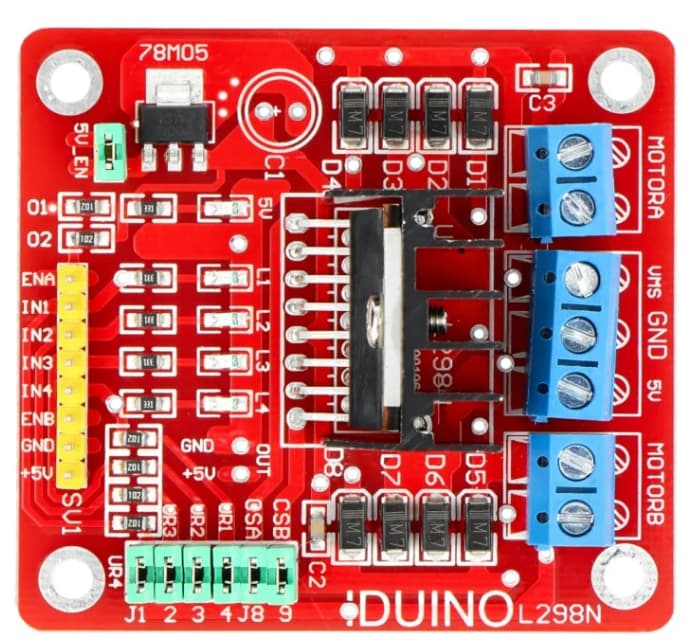
I want to mention that I am a beginner and I have searched everywhere on the internet for a motor driver module (the one I used and wanted, keyes l298, with the attached image), but I can’t find this module. I need it especially for the pcb part.
Can someone help me with the model or a link where the exact model is found. Thanks in advance!
That is likely because there is nothing to connect to the pcb layer as there are headers on the board and screw terminals. Are you planning on unsoldering the headers and screw terminals (in which case a part with a pcb layer could be made?) To do that we would need a web site for the exact board you want to use to get the correct positioning in pcb.
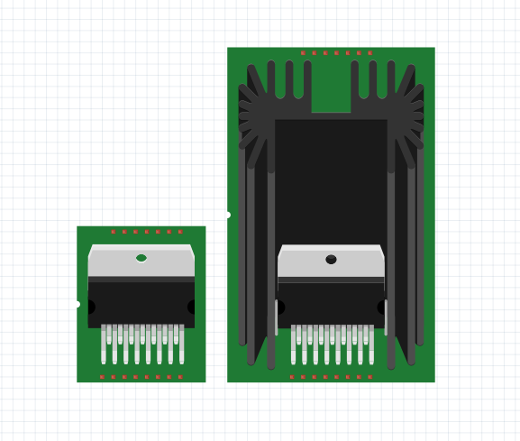
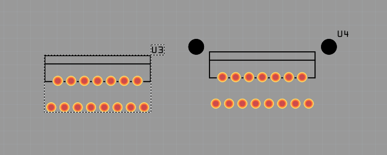
This part should do what you want. Pcb view has been added for the 6 input pins. Note if you want mounting holes you need to drag the core parts pcb hole part in to the sketch, move it over the hole in silkscreen and set the size appropriately.
Thank you so, so much! I really appreciate it.
I have one more request, if possible — I would truly be grateful.
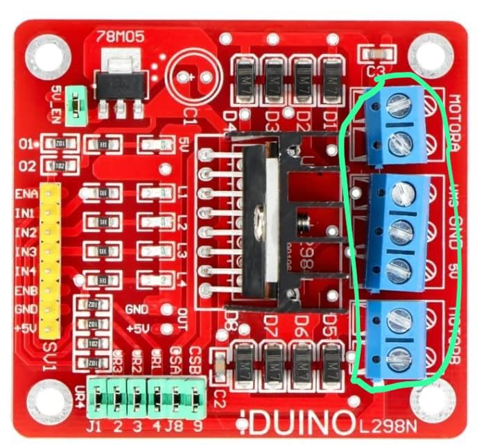
Could you also generate the power supply pins at the top + motorA/motorB as well?
What power supply pin? The only ones I see are on the screw terminals and trying to remove those is likely to cause problems. I am assuming you are leaving the screw terminals attached as attempting to remove them may make things no longer work.
Likely won’t work. The headers are likely not on 0.1in centers and headers won’t fit. I also don’t have an exact position for the holes in pcb for the headers nor the size of the holes.
Just FYI, depending on the type of screw terminal used (they don’t all use the same spacing) I have been able to do something like this by removing every second pin on a standard header. So, by removing the middle pin on a standard 3-pin header, for example, I get a 2-pin header that can replace a double screw terminal. Similarly, I could use a 5-pin header, remove the second and fourth pins, to make a 3-pin header that would replace a triple screw terminal.
If you want pads in pcb for those headers you likely need to remove the screw terminals then measure the distance from both the top and right board edges (preferably to the center of the hole) and the distance between the holes. I would need those measurements to place the headers you want in pcb. There are not any images which give the posiion of those holes that I have seen.