Hi, I have a AXICOM d2n 5v relay. This does not function the way I expected. This is how I want my relay. It only needs 8 pins as in the axicom. numbering the pins 1 to 6. number 1 being closest to the coil input. 3 pins on each side as in the d2n.
When coil is not activated pin 1 is connected to pin 2. pin 2 not connected to pin 3. This is like the d2n. When the coil is activated pin 2 is connected to pin3 and pin 1 not connected to pin 2. This is not like the d2n. There is no connection between pin 2 and 3 as measured with a multimeter continuity test. I want there to be a connection in my relay as then I can reverse the polarity to a linear actuator. I can see no way to do it with the d2n.
I am sure in the long distant past I had such a relay. Havn’t used them for yonks now. Used transistors and ICs.
Can anybody tell me where I can get such a relay and what it would be called? Thanks.
You would be better to use an H-bridge motor driver for this rather than a relay. However to do it with a relay you need to connect the common pins to the motor and the NC and NO pins to the power supply with the polarities reversed like this
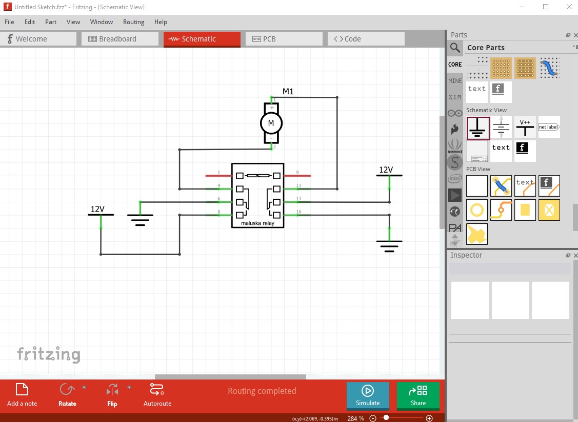
You would need a second relay to interrupt the 12V line so the motor will stop as at present the motor will always run one way or the other.
Peter
Hi, thanks for the suggestion of a H bridge driver. Will look into that. Just a point on your schematic. If the coil is not activated pin 4 connects to 6 and 11 to 13 making the motor run one way. But when coil activated 6 does not connect to 8 so you have no circuit to the motor. This is why I need a relay that connects 6 to 8 when the coil is activated. Axicom d2n does not do that.
If you have such a relay you connect battery positive to pin 6 and negative to pin 13 and then you will get the motor to run in both directions by powering or not powering the coil. If you want the motor to stop just disconnect the 12v supply.
Anyway as you suggest a H bridge motor driver may be the way to go.
From the data sheet the Axicom d2n appears to be a standard dpdt relay the same as the one I used in the schematic. As a result with the coil not active the motor will run one direction with the coil activated the motor will run the other direction (at no time will it stop, you would need a second relay or an H bridge driver for that.) Your problem is that you are using the wrong terminals on the relay. Pins 4 and 13 are the commons (which need to connect to the motor.) The power needs to connect to 6 and 9 for ground and 8 and 13 for power (or the opposite direction which will also work) and then the circuit works as you want it. The motor will see the power reverse when the coil is activated.
Peter
still lost on the connections . if you have + of battery on pin6 and - on pin 11 it will work one way. without coil activation pin 6 is connected to pin4 which can be connected to one terminal of the motor. pin 11 is connected to pin13 which can be connected to the other terminal.
When the coil is activated pin 6 is not connected to 8 or 11 to 9. Perhaps like me you are thinking they would be connected. cannot see how you can use pins 8 and 9 unless you maybe could use diodes somehow.
would a more complete circuit diagram illuminate this. showing + or - connections to pins 8 and 9 and how they connect to the motor?
It is fairly simple. Pin4 and pin 13 are the common connections. pin 4 switches between pin6 and pin 8 if pin 6 is gnd and pin 8 is 12V, pin 13 switches between pin 11 and pin 9 so pin 11 needs to connect to 12V and pin 9 needs to connect to gnd. The motor connects to pin 4 and pin 13. With the coil not energized pin 4 connects to gnd on pin 6 and the other side of the motor on pin 13 connects to 12V on pin 11 and the motor runs one direction. When the coil is activated the relay changes to pin 4 connected to 12V from pin 8 and pin 13 changes to gnd from pin 9 reversing the polarity on the motor and causing it to run the other direction.
Peter
got it now. couldn’t at first see which pins were connected when coil was activated. it wasn’t what I expected from past experience with a relay. now all working for moving linear actuator in both directions and stopping when required.
but I may end up using a H bridge motor driver if simpler to use. has the obvious advantage of no moving parts. my axicom d2n 5v can fit on solderless breadboard. I will want the H bridge also to fit on breadboard for easy prototyping. dip type probably.
just one further thing about the 5v axicom. I used 12v at the coil at one stage because I was also using 12v on the relays. the axicom was getting hot. not sure from the data sheets if you can use higher voltages on the 5v. the data sheets are not clear on that .
thanks for your patience with me on this Mr Vanepp. I can see others giving up on me. still curious about the numbering of the pins on the d2n. there are only 8 pins so why don’t they just label them from 1-8 instead of the numbers they were using. part of my confusion came from this. Thanks again.
Likely because the pins are numbered as they would be if the relay was a DIP IC so the pin number match that.
Peter