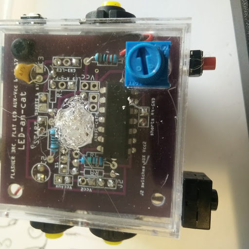
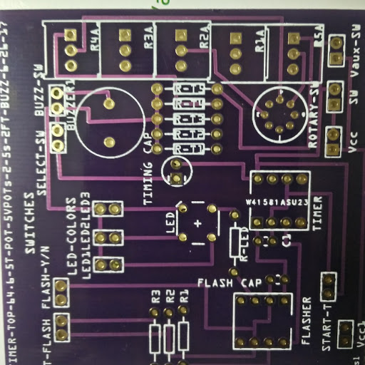
Hi, built this 556 timer-flasher many times with a NE556, always worked. Made this triple one with NE556’s and can get it to flash not time! Put a LM556 in its place and works perfectly. Never had to do this before, but put a 0.01uF on #3 and #11 and #4 to Vcc and still doesn’t time. What is really weird, I built one 2 weeks ago with LM556 at ends (thought it was a NE556) and a NE556 in the middle and they all worked fine, don’t get it! I thought NE556 and LM556 were interchangeable.
thanks, I thought it might be a bad NE556 bunch I had gotten (Taiwan) all 10 didn’t work so got a bunch from TI and supposedly another manufacturer from DIGIKEY, none of them would TIME, just FLASH. Only the LM556 worked. This made no sense, looked at the datasheet, checked the circuit over and over, compared it to previous circuits that worked with NE556, no difference in connections or main components. It has to be something very simple that I am overlooking, but it is driving me crazy that I cant find the problem.
I wonder if the current draw is greater for some unknown reason with the NE chips. I also do not see any decoupling caps on your board. I would try adding a 100nf cap to each chip to see if they work.
Edit: I looked again and see that C1,C2,C3 may be a decoupling caps. Are they big enough?
Good catch! That (especially with the leds) is a likely culprit. If when the leds switch on, VCC drops due to not enough bypass caps (I’d stick a couple of 10uf or so caps in) odd results are likely. If you have a scope, put it on the VCC line and see if it is indeed dropping.
thanks, sorry I thought I had indicated that I usually didnt put 0.01uF caps on the control pin and reset to Vcc, did that and still no dice! The only difference with this circuit and others was I used a 9v adapter instead of a battery.
can you try the battery in place of the adapter in this circuit easily? A change in VCC voltage is still a likely culprit here and a battery will provide a more stable VCC than the adapter. I remember an old (20 or so years old) example of this with a PIC micro. Program the PIC to flash a led (no bypass capacitors on VCC). With a single LED works as expected but adding 2 or 3 more LEDs causes VCC to collapse due to no bypass caps and the the PIC malfunctions as VCC drops. It is possible that something similar is happening here.
tried just the battery, no go! have built this circuit several months before with round LEDs worked fine. What is strange is I built this same circuit with same PCB same components just LM556-NE556-LM556 ceramic 10uF caps for timer, no bypass caps no reset to Vcc and worked and is still working.
yes there is something odd! all of a sudden the LM556 didn’t work, then the NE556 worked!! The board was bad, had an intermittent open! probably why the first one I made worked fine. have 5 boards and two that I know of are bad, my luck to have picked one bad one after another. I didn’t expect a PCB board to be bad! Live and learn.
thanks for all your suggestions, made me look into it further and notice that sometimes there was voltage at #14 and a few seconds later 0v.
btw both the LM and NE worked without the cap.
On a new board, the NE556 only flashes, doesn’t time and most importantly doesn’t get hot!
Three curious things happen: 1. doesn’t time, 2 keeping trigger constantly low, it constantly flashes but at half the rate for the given cap and R!, 3. voltage Vcc-#7 (#1-556) during constant flashing oscillates between 4.6-5.9v and on the LM556 it is a constant 3.24v (same as the control voltage pin) put a 0.01uF cap on control voltage to GND and oscillates between 3.8-4.1v, control voltage on the NE(which was a constant 3.14, like the LM) now oscillates between 3.0-3.3v.
The LM works perfectly! even without a cap on the control voltage or reset to Vcc.
I realize the simple solution is just use the LM556 but I have used the NE556 as a single timer-flasher many times (without a cap on the control voltage) with no problem. The first board with this sketch and a NE556 in the middle worked perfectly. Replicated it several NEs and the NE still doesn’t time.
Although it is great that you still have the knowledge to make fully analog circuit. What I do not understand is why when you can buy an Arduino Pro Mini for $2 delivered and Ws2812 Individually addressable LEDs 10 for $0.99 on breakout boards delivered anyone would spend the time and expense to make a dedicated analog circuit to flash three LEDs. (I assume it is scale model related)
With the Rocketscream low power library it is really easy to make the Arduino consume very little power. Then add the ease of use of a Individually addressable LEDs with FastLed.io library and I could have your circuit complete and programmed in under 20 minutes and it would not consume anymore power.
I take your point, but I was completely new to all of this in Jan 2017. Had never designed a PCB or for that matter ever heard of a 555 timer! Didnt know Arduino existed until March and still dont know what all the capabilities it offers. In Jan., just wanted to have a timer that powered an LED for 10 seconds. I knew a resistor and a large capacitor would do that but the cap would be too large! Since you cant buy just 3 of anything on Amazon I had all these left over components. I decided to make cool flashers and timers for my 9 grandkids! Its been fun and enjoyable to design the PCBs and then see them work! I now know something about 555, 556 timers, how to make different timers or a flasher, more about LEDs than I needed, Fritzing and sites like this one. Before January I had no clue to any of this.
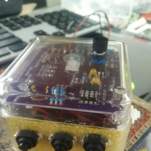
Do you have any idea how tedious it was to put a PCB timer-flasher with a 556 and fit it in a plastic case 2 x 2 x 3/4 inches, drill drill 14 holes for he switch wires,have adjustable flash rate, switches to choose the color of the RGB led, have it flash or not, have it stay on for 1 or 8 minutes, indicator LED so they will know its on, all with my big fingers, each one took a full day! One of the grandkids took it to a “show and tell” in class and was asked by many of his classmates, “can your grandfather make me one” dont think an Arduino would have elicited the same response.The smile on his face telling me about it was worth every minute of tedium! But since you have just schooled me to what an Arduino can do, rest assured I will check it out, thank you!
WHAT I HAVE DONE SINCE JANUARY, besides the initial project of the three flashers :
Great work. I had thought you were someone that had worked with analog circuits in the past as many of us have done. Understanding analog circuits is very important even when using microcontrollers when dealing with sensors and communication lines so do keep learning and building analog circuits. If you want to learn about microcontrollers I would suggest checking out Adafruit. They have many great tutorials involving Arduino’s. You may still have to solder but not as much as building your own PCBs.
This is a Warp Core model I built using an Arduino Pro Mini and 37 individually addressable LEDs. The LEDs work in series by passing on serial data from one to the next. This means only the very first LED is connected to the Arduino. Each LED can display 16,777,216 colors and can be controlled really easily. https://www.thingiverse.com/thing:2008591
The getting hot part is possibly important, because that indicates an overload (and may have damaged the chips). I assume your power supply is a non regulated 5 volt wall wart (simply because of the voltage change, a regulated wall wart should always provide 5 volts)? It would be interesting to measure the current going in to VCC with each type of chip installed. The change in voltages indicates something is drawing too much current (or just more than the power supply can supply). A variation in the voltages can affect the timing values of the 556 depending where in the timing cycle they are occurring.
This obviously has been intriguing me for awhile! the first board worked perfectly LM-NE-LM, the second NE-NE-NE and third did not and then did but only partially. I built the third board with 556 sockets so I can interchange ICs. When I use a new NE556 in the socket it reads the same voltages as the NE556 in the second board where the 556s are fixed! Unlikely they are all fried. Like you, also interested in the current so I designed a new board that allows me to measure the current at each NE556 not just the entire circuit. Before all the NEs got hot now they dont??? Awaiting the board, stay tuned.
BTW, It was a 9V adapter. A 9V battery had the same effect, so dont think it is the supply.
Les
I’d suggest that one of the breadboards (like the one in Fritzing breadboard view) is a better bet for experimenting that pcbs. You can change the circuit around to test things without needing to wait for boards. It the power supply is 9V then VCC should be 9V (not 4.5 to 5V). That would indicate your circuit is drawing more current than the power supply can supply and thus the output voltage drops.