** NE555 DC 12V Power Relay Module**
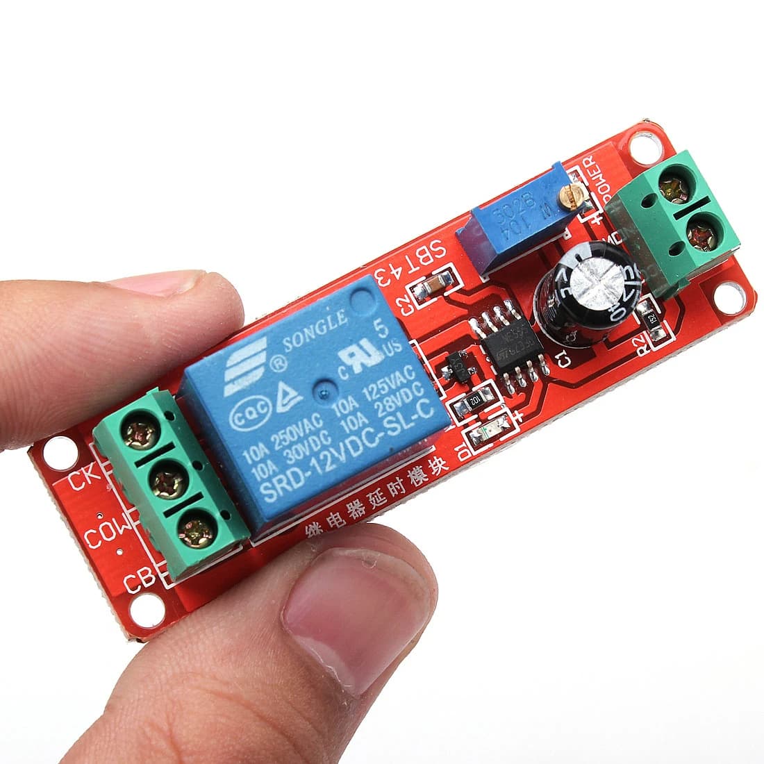
Time delay relay module
**Previous work, relay module **
[June – 2018 – Omnigatherum] (June – 2018 – Omnigatherum)
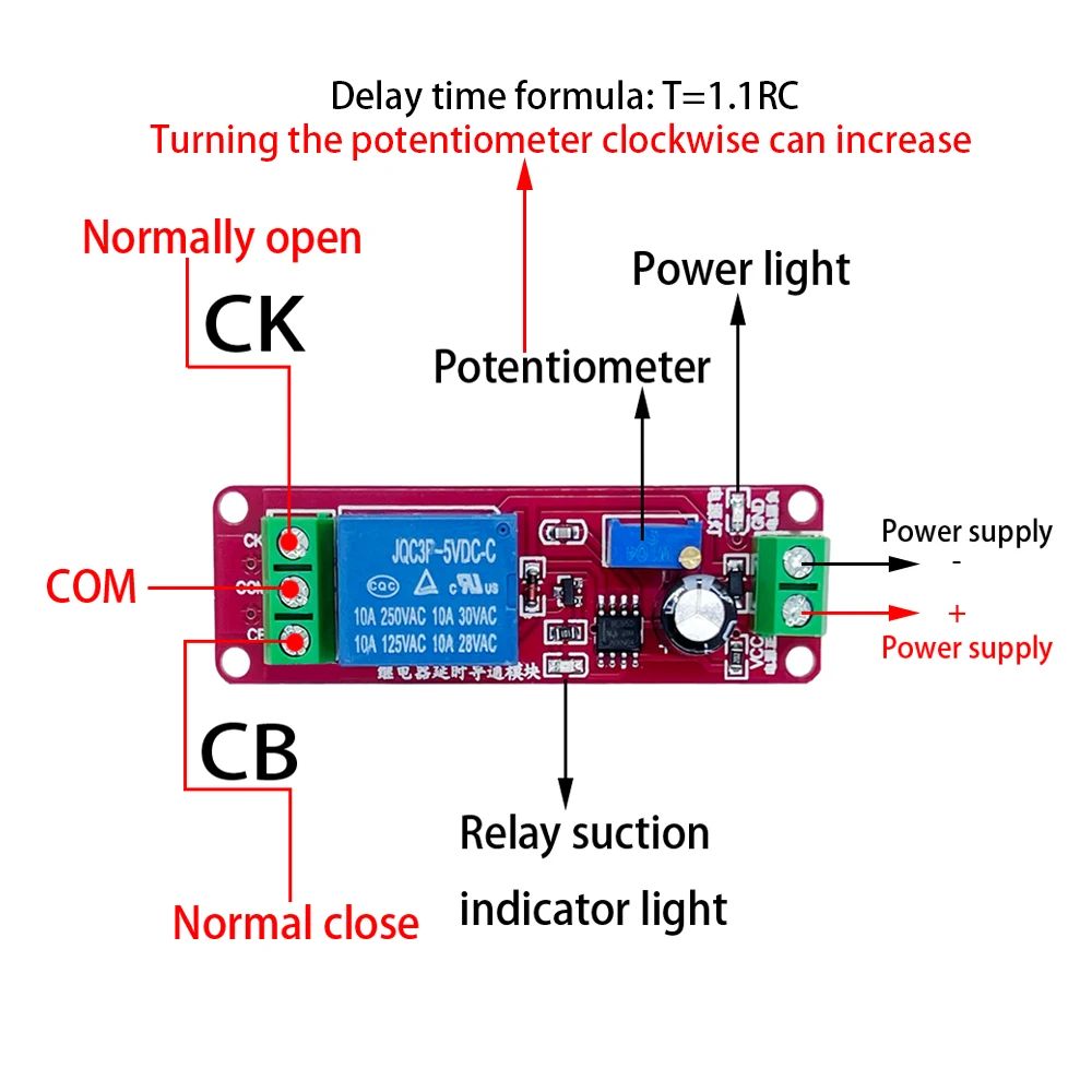
Top view
This picture shows the part from above
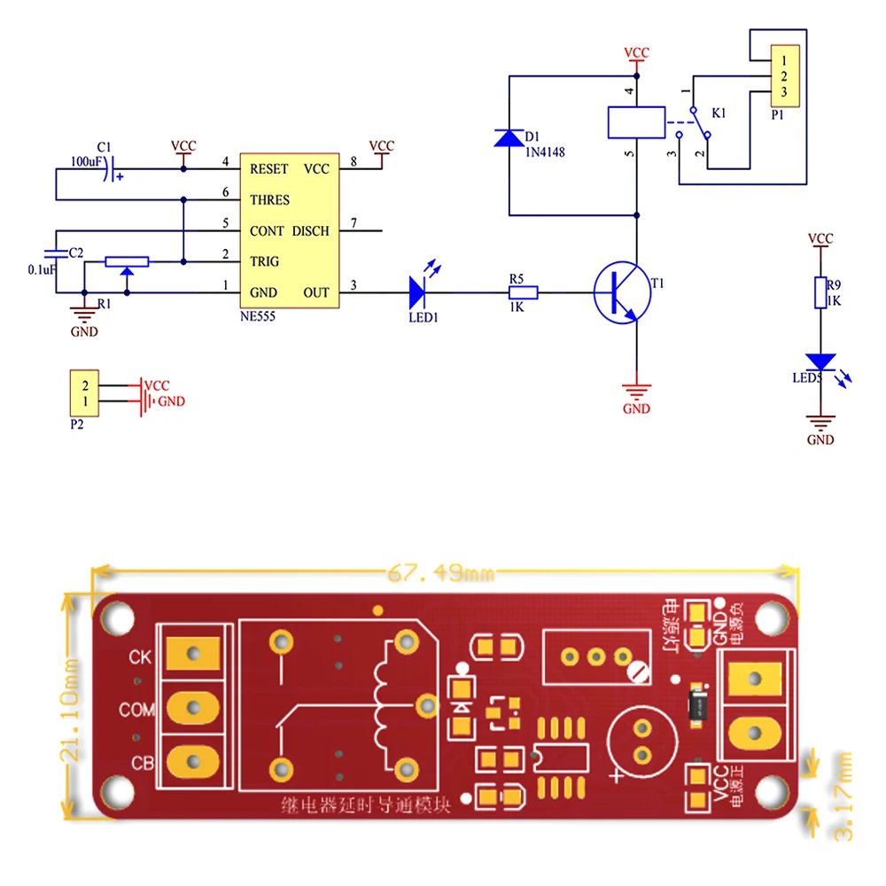
Datasheet
NE555 DC 12V 10A Timer Delay Relay Module. (pixelelectric.com)
Type
I did not read this
Breakout board, sub assembly, plug in module (A)
Antenna (AE)
Battery (BT)
Capacitor (C)
Diode (D)
Display (DS)
Fuse (F)
Hardware , mounting screws, etc. (H)
Jack, fixed part of a connector pair, header (J)
Relay (K)
Inductor, Coil, Ferrite bead (L)
Loudspeaker, Buzzer (LS)
Motor (M)
Microphone (MK)
Plug, moveable part of a connector pair (P)
Transistor (Q)
Resistor (R)
Thermistor (RT)
Varistor (RV)
Switch (S)
Transformer (T)
Integrated Circuit (IC)
Crystal, Oscillator (Y)
Zender diode (Z)
Other (please specifiy)
Footprint
E.g. SOT23-5 , TO-220.
This usually does not apply to breakout boards.